TM 5-3895-359-14&P
3. Install the Woodruff keys for the gears in both shafts.
4. Note that the teeth on one gear form a right-hand
helix and on the other a left-hand helix. When viewing
the engine from the flywheel end, the gear with right-
hand helical teeth is located on the left-side and the
gear with left-hand helical teeth is located on the right-
side of the engine. With this in mind, rest the non-gear
end of the camshaft on a wood block and start the gear
on the other end of the shaft by hand so the keyway
aligns with the key and with the flat finished face of the
gear away from the bearing.
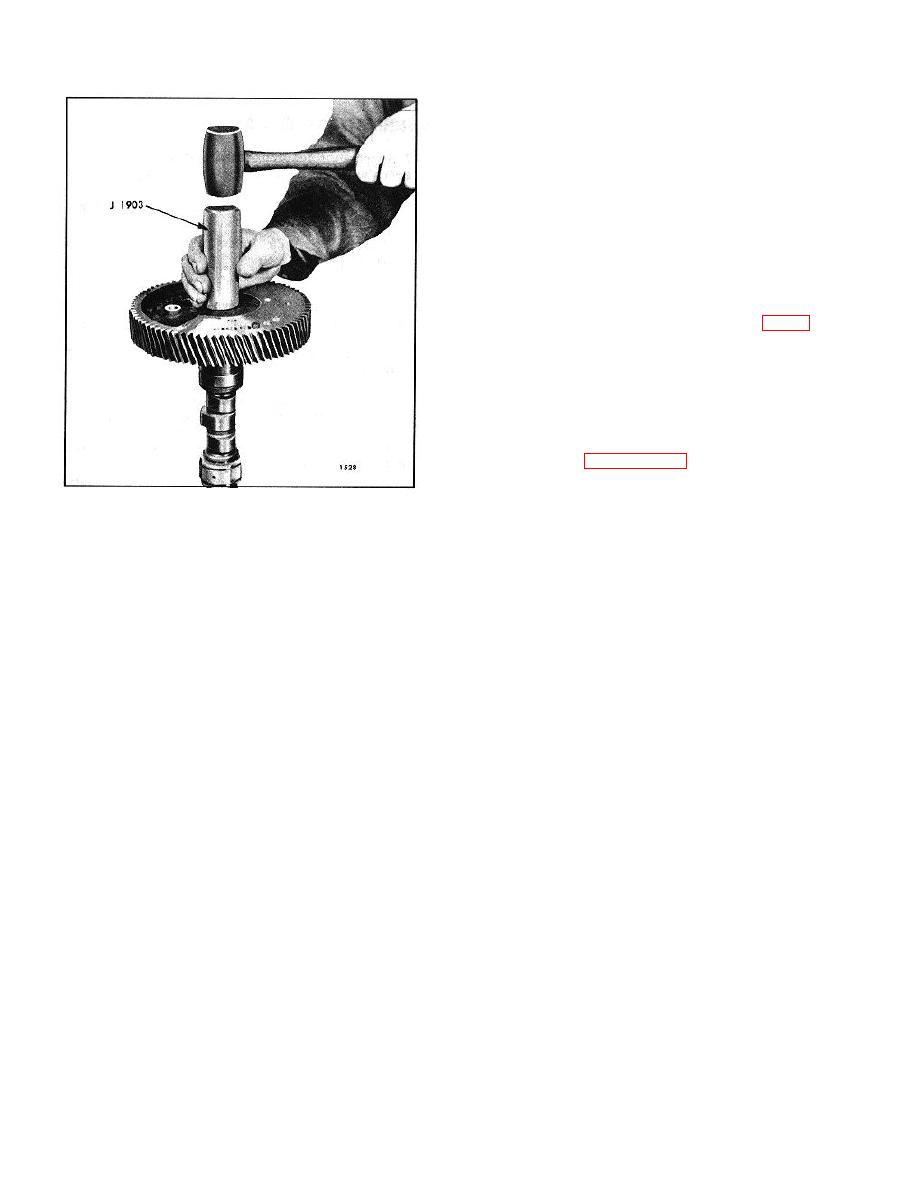
5. Use gear installer J 1903 as shown in Fig. 3 to drive
the gears on the camshaft and balance shaft.
6. Start the gear retaining nuts on their respective
shafts by hand. Tighten the nuts after the shafts have
been installed in the cylinder block.
7. Install the camshaft and balance shaft in the engine
as outlined on Page 10-2-113.
8. With the shafts and the front balance weights
Fig. 3. Replacing Gear (Camshaft Shown)
installed, wedge a clean cloth between the camshaft and
balance shaft gears and tighten the gear retaining nuts
Install Camshaft and Balance Shaft Gears
to 300-325 lb-ft (407-441 Nm) torque.
1. Install the balance weights, if removed, on the gears.
9. Secure the nuts with retainers, retainer bolts and lock
washers.
2. Lubricate the shaft journals and place the camshaft
and balance shaft end bearings in place, with the bolting
10. Check the backlash between the mating gears. The
flanges facing toward the gear ends of the shafts.
backlash should be .003 "-.008 " with new parts or.010 "
maximum with used parts.
10-2-116


