TM 5-3895-359-14&P
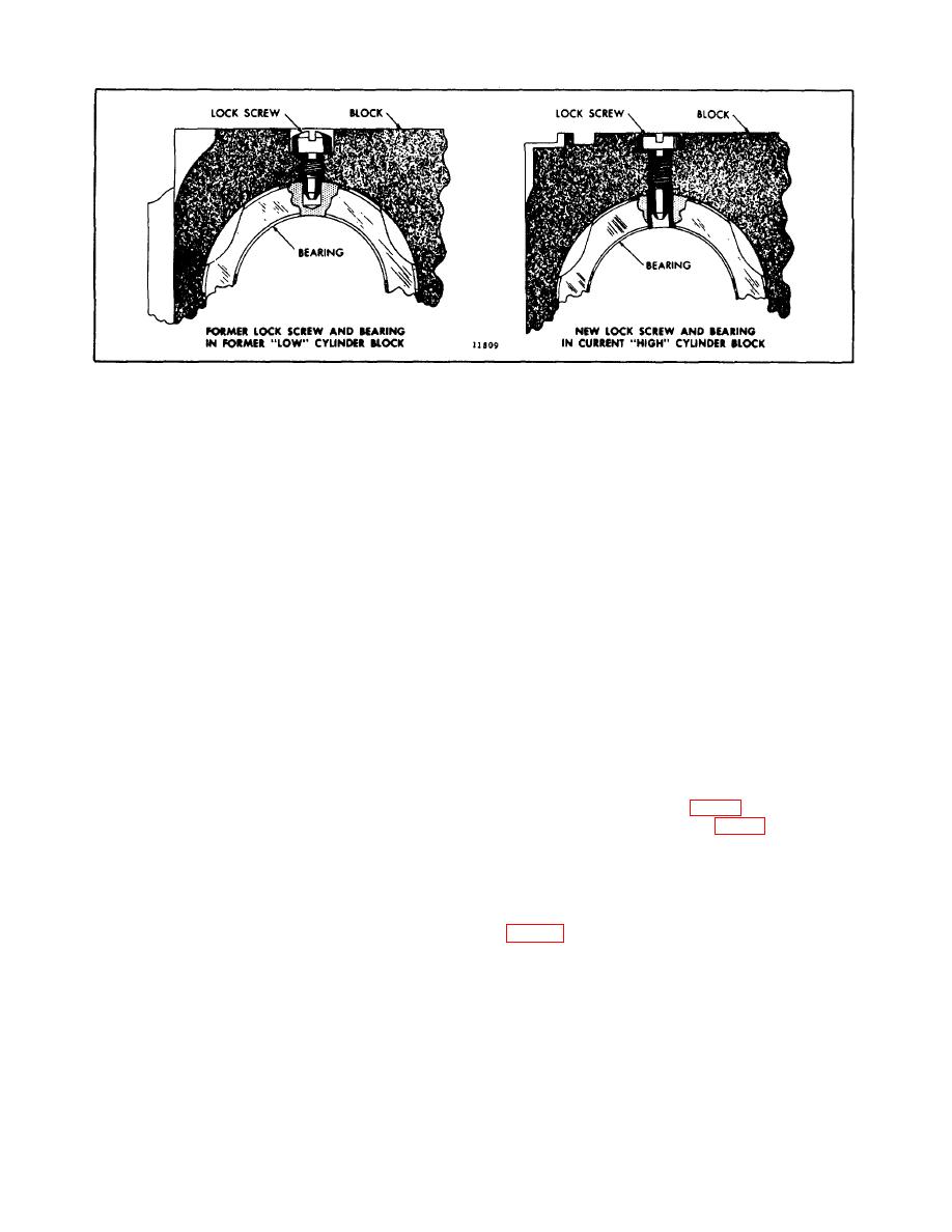
Fig. 13. Camshaft Intermediate Bearing Lock Screws
2. Align the key in the shaft with the keyway in the
and balance shaft gears to prevent their turning.
camshaft drive gear and start the shaft into the gear.
Tighten the nuts to 300-325 lb-ft (407-441 Nm) torque.
Tap the shaft into the gear with a soft (plastic or
rawhide) hammer.
14. Install the camshaft and balance shaft gear nut
retainers with bolts and lock washers. Tighten the bolts
3. Remove the camshaft gear puller, spacers and
to 35-39 Ib-ft (47-53 Nm) torque.
adaptor plate. Finger tighten the gear retaining nut on
the shaft.
15. Check the clearance between the thrust washer and
the thrust shoulder of both the camshaft and balance
4. Install the front end bearing and thrust washers with
shaft. The specified clearance is .004 " to .012 " with
the bolts and lock washers. Tighten the bolts to 35-40
new parts or a maximum of .018 " with used parts.
lb-ft (47-54 Nm) torque.
16. Check the backlash between the mating gears. The
specified backlash between new gears is .003 " to .008 "
NOTE:
or a maximum of .010 " between worn gears.
Apply grease to the steel faces of the
thrust washers and insure that the
17. Install the flywheel housing and other parts or
steel faces are towards the bearing.
assemblies that were removed from the engine as
outlined in their respective chapters of this manual.
5. Install the balance weight on the front end of the
camshaft.
18. Refill the cooling system.
6. Start the balance weight retaining nut and lock
Install
Camshaft
(Flywheel
Housing
and
washer on the camshaft (Fig. 8). Place a wood block
Transmission in Place)
between the balance weights (Fig. 4). Tighten the gear
retaining nut and the balance weight nut to 300-325 Ib-ft
1. Install a Woodruff key in the drive gear end of the
(407-441 Nm) torque.
camshaft and insert this end into position from the front
end of the engine. Push the shaft in until it slides into
7. Align the holes in the camshaft intermediate bearings
the rear end bearing. Use care in the installation of the
with the tapped holes in the top of the cylinder block
camshaft to prevent damage to the cam lobes.
lb-ft (20-27 Nm) torque.
IMPORTANT:
Install the woodruff keys in the
8. Reinstall the parts, accessories and assemblies that
were removed from the engine as outlined in their
current advanced timed camshafts as
respective chapters in this manual.
outlined in the service note under
Advanced Timed Camshaft.
9. Refill the cooling system.
10-2-114


