TM 5-3895-359-14&P
CAMSHAFT AND BALANCE SHAFT GEARS
The camshaft and balance shaft gears, located at the
2. Support the camshaft suitably in the soft jaws of a
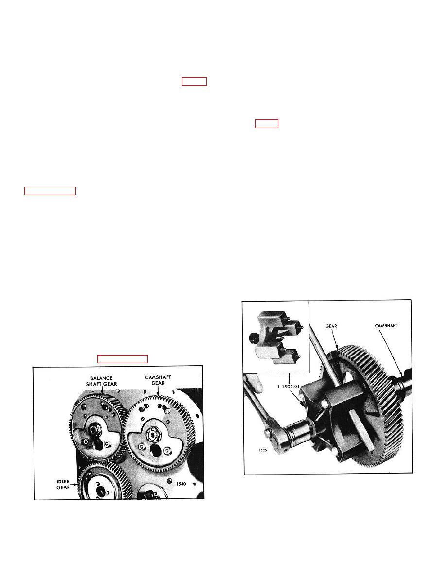
flywheel end of the engine, mesh with each other and
bench vise, being careful not to damage the cams.
run at the same speed as the crankshaft (Fig. 1).
Viewing the engine from the flywheel or gear train end,
3. Remove the nut retaining the gear on the camshaft.
the right-hand gear, (camshaft) has left-hand helical
teeth and the left-hand gear has right-hand helical teeth.
4. Back out the puller screw of tool J 1902-01 and
The idler gear mates with the left-hand gear.
attach the puller to the outer face of the gear with four
bolts (Fig. 2).
Since the camshaft and balance shaft gears must be in
time with each other, the letter "O" is stamped on one
5. Turn the puller screw down against the end of the
tooth of one of the gears with a corresponding mark at
shaft to remove the gear.
the root of the mating tooth of the other gear. Also,
since these two gears as a unit must be in time with the
6. Remove the gear from the balance shaft in a similar
crankshaft, identification marks (letter "R") are located
manner.
on the camshaft gear and the mating idler gear, (refer to
7. If necessary, remove the two weight retaining bolts
and remove the balance weights from each gear.
The camshaft and balance shaft gears are keyed to their
respective shafts and held securely against the
8. If necessary, remove the keys from the camshaft and
shoulder on the shaft by a nut. A gear nut retainer, with
balance shaft.
a double hexagon hole in the center, fits over the nut
and prevents loosening of the nut. The retainer is
Inspection
attached to the gear by bolts threaded into tapped holes
in the gear. These tapped holes are also utilized in
Clean the gears with fuel oil and dry them with
mounting an accessory drive on the camshaft or
compressed air. Then examine the gear teeth for
balance shaft gear.
evidence of scoring, pitting and wear. If severely
damaged or worn, install a new gear. Also check the
A small balance weight is attached to the inner face of
other gears in the gear train.
each gear. The weight is secured with two 3/8"-24 x 1-
3/8" bolts. These weights are important in maintaining
perfect engine balance.
Remove Camshaft and Balance Shaft Gears
1. Remove the camshaft and balance shaft from the
engine as outlined on Page 10-2-108.
Fig. 2. Removing Gear (Camshaft or Balance Shaft)
Fig. 1. Camshaft and Balance Shaft Gears
10-2-115


