TM 5-3895-359-14&P
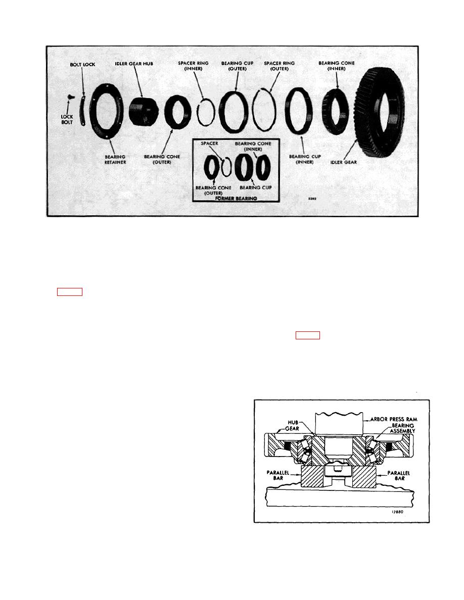
Fig. 4. Idler Gear Details and Relative Location of Parts
5.
Install the inner spacer ring on the idler gear hub
Examine the gear teeth for evidence of scoring, pitting
so that the oil hole in the hub is 180from the gap in the
and wear. If severely damaged or worn, replace the
inner spacer ring.
gear. Also, inspect the other gears in the gear train.
6.
Position the gear with both cups over the hub and
Assemble Idler Gear, Hub and Bearing
the inner bearing cone.
Refer to Fig. 4 and assemble the bearing components
7.
Press the outer idler gear bearing cone over the
in their original positions (refer to identification marks
hub while rotating the gear to seat the rollers properly
made during disassembly) as outlined below:
between the cones.
The bearing cones must be
supported so as not to load the bearing rollers during
NOTE:
The current idler gear
this operation (Fig. 5).
bearing is a matched assembly. Do
not mix components.
8.
Before installing the gear and bearing assembly,
check the pre-load.
1.
Support the idler gear, shoulder down, on the bed
of an arbor press. Start one of the bearing cups,
numbered side up, squarely into the bore of the gear.
Then press the bearing cup against the shoulder of the
gear. Use a flat steel plate (pre-load test plate) between
the ram of the press and the bearing cup.
2.
Lay the outer spacer ring on the face of the
bearing cup.
3.
Start the other bearing cup, numbered side down,
squarely into the bore of the gear. Then press the cup
tight against the spacer ring. Use a flat steel plate (pre-
load test plate) between the ram of the press and the
bearing cup.
4.
Press the inner bearing cone (numbered side up)
on the idler gear hub, flush with the inner hub mounting
face. Use the pre-load test plate (with the large center
Fig. 5. Pressing Hub into Bearing
hole) between the ram of the press and the bearing.
10-2-119


