TM 5-3895-359-14&P
If the crankshaft and camshaft gears are mounted on
A scale reading which exceeds the specified maximum
the engine, a suitable fixture, which may be held in a
indicates binding of the bearing rollers, or rollers
vise, can be made as shown in Fig. 6. Three plates
improperly installed. When the scale reading is less
(shown in Fig. 7) a 1/2"-13 x 2 3/4" bolt and a plain
than the specified minimum, the bearing is more likely
washer are used with a 1/2 "-13 nut and plain washer for
worn and should be replaced.
mounting. One of the plates is used to take the place of
the flywheel housing, and the other two plates, the
After the pre-load test is completed, remove the steel
cylinder block, Engine-mounted conditions are simulated
plates and install the bearing retainer as follows:
by tightening the nut to 80-90 lb-ft (108-122 Nm) torque
and tightening the three plate-to-hub attaching bolts to
1.
Attach the bearing retainer to the idler gear with
25-40 lb-ft (34-54 Nm) torque.
six bolts and three bolt locks. Tighten the bolts to 24-29
lb-ft (33-39 Nm) torque.
Check the pre-load as follows:
IMPORTANT:
New locking bolts
1.
Attach the plates (two upper plate shown in Fig 7)
should always be used when
to the idler gear with 1/2"-13 bolt, washers and nuts as
attaching the bearing retainer to the
shown in Fig. 6. Tighten the bolt to 80-90 lb-ft (108122
idler gear.
Nm) torque.
2.
Bend the ears of each bolt lock against the flat
side of the attaching bolt heads to secure the bolts.
2.
Attach the third plate to the idler gear hub with
three 3/8 "-16 bolts. Tighten the bolts to 25-40 Ib-ft (34-
Install Idler Gear, Hub and Bearing Assembly
54 Nm) torque.
1.
Position the crankshaft gear and the balance shaft
3.
Clamp the idler gear assembly and fixture in vise
gear so that the timing marks will align with those on the
idler gear (refer to Fig. 1 on Page 10-2-103).
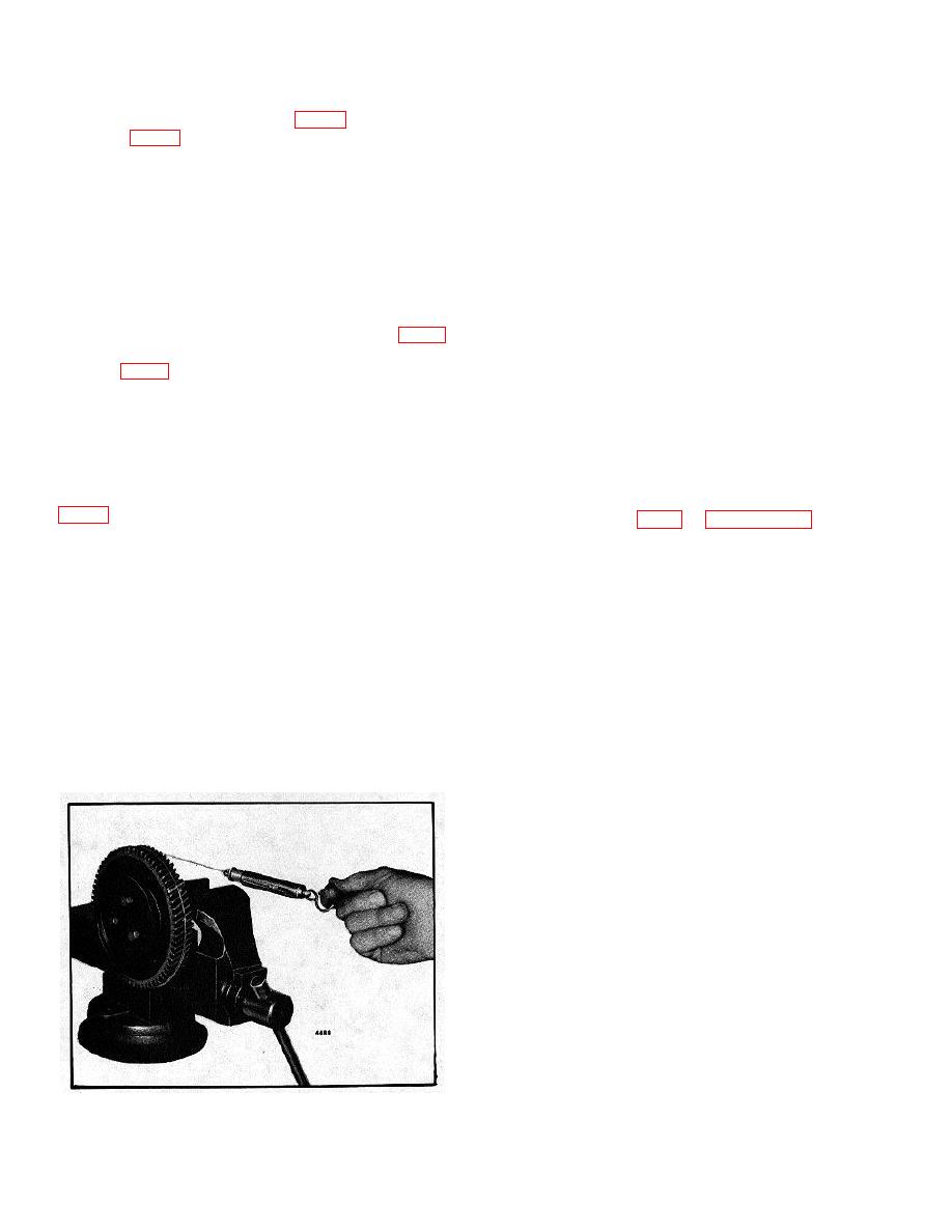
4.
Attach the cord to the idler gear and spring scale
2.
With these marks in alignment, start the idler gear
and check the pre-load as outlined in step 4 of the
into mesh with the crankshaft gear and the balance shaft
previous method.
gear, and simultaneously rotate the gear hub so that the
hollow dowel at the inner face of the hub registers with
If the scale reading is within the specified 1/2 to 4 lbs.,
the oil hole in the end plate.
but fluctuates more than the permissible 2 lbs. 11
ounces, the idler gear and bearing assembly must NOT
3.
Roll the idler gear into position, align the hollow
be installed on the engine. Fluctuations in scale reading
dowel with the hole in the end plate, and gently tap the
may be caused by the cones or races not being
hub until it seals against the end plate. Thus the hollow
concentric to each other, damaged cones or races or
dowel in the hub will conduct oil through the end plate
rollers, or dirt or foreign material within the bearings. In
and into the hub where it flows through a drilled passage
these cases, the bearing should be inspected for the
to the roller bearing.
cause of fluctuation in the scale readings and corrected
or a new bearing installed.
4.
After making sure that the hub is tight against the
end plate, secure the idler gear assembly with a 1/2 "13
bolt and special washer. Tighten the bolt to 80-90 lb-ft
(108-122 Nm) torque.
5.
If previously removed, install the idler gear hole
spacer (dummy hub). Secure the spacer to the cylinder
block end plate and cylinder block with a 1/2 "-13 bolt
and special washer. Tighten the bolt to 80-90 lb-ft (108-
122 Nm) torque.
NOTE: Current engines use a new
idler gear hub and idler gear hole
spacer (dummy hub) which requires
1/2 "-13 x 2-1/2" retaining bolts,
replacing the 1/2"-13 x 2" bolts
formerly used.
6.
Lubricate the idler gear and bearing liberally with
Fig. 8. Checking Pre-Load of Idler Gear Bearing
clean engine oil.
10-2-121


