
TM 5-3895-359-14&P
The non-turbocharged (naturally aspirated) engines use
an 18.7:1 compression ratio piston and the turbocharged
engines use a 17:1 compression ratio piston. To aid
identification of a piston, refer to Fig. 3. Fit the end of
the gage between the top of the piston crown and the
machined step below the third compression ring groove.
A "GO" check identifies a piston used in a turbocharged
engine. A space of approximately .030" ("NO-GO")
identifies a piston used in a naturally aspirated engine.
NOTE
Cross-head pistons and trunk-type
pistons must not be used together in
an engine. The difference in weight
of the pistons will affect engine
balance.
Inspect Piston Rings
When an engine is hard to start, runs rough or lacks
power, worn or sticking compression rings may be the
cause. Replacing the rings will aid in restoring engine
operation to normal.
The compression rings may be inspected through the
ports in the cylinder liners after the air box covers have
been removed. If the rings are free and are not worn to
the extent that the plating or grooves are gone,
compression should be within operating specifications.
Refer to Page 10-11-9 for the procedure for checking
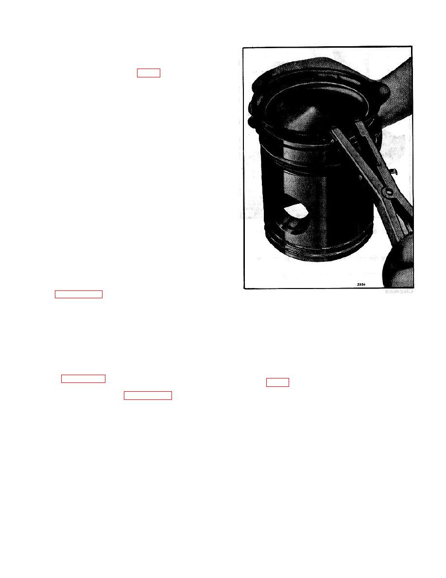
Fig. 4. Removing or Installing Piston Rings using
compression pressure.
Tool J 8128
Remove Piston and Connecting Rod
Disassemble Piston and Connecting Rod
1. Drain the cooling system.
Note the condition of the piston and rings. Then remove
the rings and disassemble the piston as follows:
2. Drain the oil and remove the oil pan.
1. Secure the connecting rod in a vise equipped with
3. Remove the oil pump and inlet and outlet pipes, if
soft jaws and remove the piston rings with tool J 8128 as
necessary (Page 10-5-6).
shown in Fig. 4.
2. Punch a hole through the center of one of the piston
4. Remove the cylinder head (Page 10-2-20).
pin retainers with a narrow chisel or punch and pry the
retainer from the piston, being careful not to damage the
5. Remove the carbon deposits from the upper inner
piston or bushing. Remove the opposite retainer in the
surface of the cylinder liner.
same manner.
3. Loosen the two bolts which secure the connecting rod
6. Remove the bearing cap and the lower bearing shell
to the piston pin. Then remove the rod and piston
from the connecting rod. Then push the piston and rod
assembly from the vise and place the assembly on the
assembly out through the top of the cylinder block. The
bench. Remove the two bolts and spacers and remove
piston cannot be removed from the bottom of the
the connecting rod.
cylinder block.
4. Withdraw the piston pin.
5. Separate the piston skirt from the piston crown.
7. Reassemble the bearing cap and lower bearing shell
to the connecting rod.
10-2-79
