
TM 5-3895-359-14&P
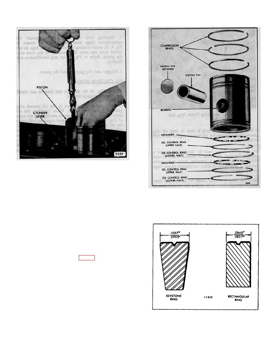
Fig. 11 - Measuring Piston-to-Liner Clearance
using Tool J 5438-01
.001" greater than the thickness of the feeler gage used,
i.e., a .004" feeler gage will indicate a clearance of .005"
when it is withdrawn with a pull of six pounds. The
Fig. 12 - Piston Ring Location (Non-
feeler gage must be perfectly flat and free of nicks and
Turbocharged Engine)
bends.
the tapered fire ring groove are available for service.
If any bind occurs between the piston and the liner,
examine the piston and liner for burrs. Remove burrs
with a fine hone (a flat one is preferable) and recheck
the clearance.
Fitting Piston Rings
Each piston is fitted with a fire ring, two compression
rings and two oil control rings (Fig. 12).
The top (fire) ring and the upper compression ring
(second groove) are pre-stressed. Both are identified by
a small indentation mark on the top side.
NOTE: The current piston crowns (18.7: 1 and
17: 1 compression ratio) have a tapered fire ring
groove. To conform with this change, a tapered
fire ring (Fig. 13) must be used. The former
piston crown (17: 1 compression ratio) had a
rectangular fire ring groove. Only pistons with
Fig. 13 Comparison of Fire Rings
10-2-83
