TM 5-3895-359-14&P
It is very important that all old gasket material be
and idler gear hole spacer, finger tight.
Remove the
pilot studs.
thoroughly removed from the flywheel housing and the
endplate, otherwise runout of the pilot and the face of
A self-locking type bolt and steel washer are currently
the housing may be affected when the housing is
being used to attach the flywheel housing to the idler
installed on the engine.
gear hub and hole spacer. With this type bolt, the
additional operation of securing the bolts with a lock wire
Remove and discard the crankshaft rear oil seal. Install
is eliminated, inasmuch as the head of the bolt is so
a new oil seal as outlined on Page 10-2-56.
designed that it will lock itself to the attaching member
when the specified torque is applied.
Install Flywheel Housing
NOTE
1. Lubricate the gear train teeth with clean engine oil.
2. Affix a new housing-to-end plate gasket to the
The self-locking bolts must be used
flywheel housing.
in sets of three.
3. Coat the lip of the oil seal lightly with engine oil. Do
not scratch or nick the sealing edge of the oil seal.
7. Install the six 1/2 "-13 housing to block bolts with
4. Thread four pilot studs J 1927-01 into the cylinder
lockwashers, finger tight.
block to guide the housing in place (Fig. 2). Use oil
8. Install the remaining flywheel housing attaching bolts
seal expander J 22425 (standard size seal) or expander
and washers, finger tight.
J 4195-01 and handle J 8092 (oversize seal) on the end
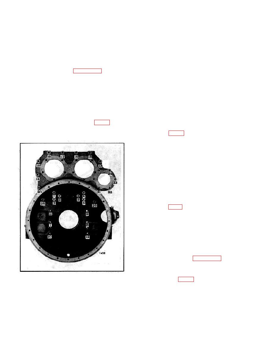
9. Refer to Fig. 3 for the bolt tightening sequence.
of the crankshaft to pilot the oil seal on the crankshaft.
Start at number I and, using the proper sequence, bring
all bolts to within 10-15 lb-ft (14.20 Nm) of their
specified torque, drawing the mating parts together
evenly.
NOTE
When tightening the idler gear hub
bolts, turn the crankshaft to prevent
any bind or brinelling of the idler
gear bearing. The crankshaft must
be rotated for the flywheel housing
bell tightening also.
10. Refer to Fig. 4 for the final bolt tightening sequence
and, starting at number 1, tighten all of the bolts to the
specified torque. Tighten the 3/8 "-16 idler gear hub and
hole spacer self-locking bolts to 40-45 lb-ft (54-61 Nm)
torque. Tighten all other 3/8 "-16 and 3/8 "-24 bolts to
25-30 lb-ft (34-41 Nm) torque, and the 1/2 "-13 bolts to
90-100 lb-ft (122-136 Nm) torque. Be sure to rotate the
crankshaft when tightening the idler gear hub bolts and
flywheel housing bell.
11. Install the flywheel (Page 10-2-72).
12. Check the flywheel housing concentricity and
bolting flange face with tool set J 9737-01 as follows:
Fig. 3. Flywheel Housing Bolt Tightening Sequence
a. Refer to Fig. 5 and thread the base post J
(Operation 1)
9737-3 tightly into one of the tapped holes in the
5. With the housing suitably supported, position it over
flywheel. Then assemble the dial indicators on
the crankshaft and up against the cylinder block rear
the base post.
end plate and gasket. Remove the oil seal expander.
6. Refer to Fig. I and install the six 3/8 "-16 bolts with
flat washers in the tapped holes of the idler gear hub
10-2-76


