
TM 5-3895-359-14&P
4. Lubricate the piston pin with clean engine oil and
install it as shown in Fig. 7.
CAUTION
Line up the piston pin opening in the
piston skirt with the bearing
(bushing) opening in the piston
crown to prevent damage to the pin
or bushing.
5. Install the spacers on the two 7/16"-20 x 2"
connecting rod to piston pin attaching bolts.
6. Apply a small amount of International Compound No.
2, or equivalent, to the bolt threads and bolt head
contact surfaces.
7. Install and tighten the bolts finger tight. Then clamp
the connecting rod in a vise and tighten the bolts to 55-
60 lb-ft (75-81 Nm) torque (Fig. 8). Do not exceed this
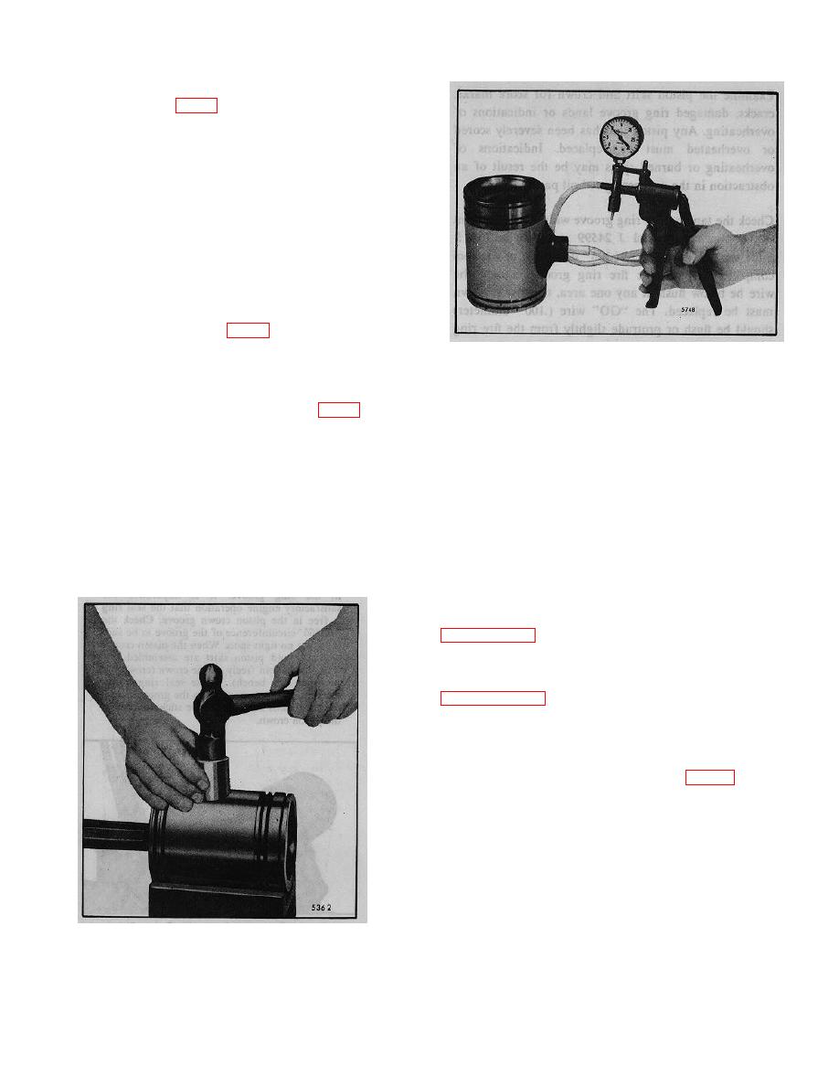
Fig. 10- Checking Piston Pin Retainer for Proper
8. Place a new piston pin retainer in position. Then
Sealing using Tool J 23987-01
place the crowned end of installer J 23762 against the
retainer and strike the tool just hard enough to deflect
10. One important function of the piston pin retainer is
the retainer and seat it evenly in the piston (Fig. 9).
to prevent the oil, which cools the underside of the
9. Install the second piston pin retainer in the same
piston and lubricates the piston pin bushing, from
manner.
reaching the cylinder walls. Check each retainer for
NOTE
proper sealing with leak detector J 23987-01 (Fig. 24).
Due to the size of the counterbore in
Place the suction cup over the retainer and hand
the piston skirt, be careful when
operate the lever to pull a vacuum of ten inches on the
installing the piston pin retainers
gage. A drop in the gage reading indicates air leakage
and inspect them to be sure they are
at the retainer.
not buckled and that they are fully
seated in the counterbore. The width
Fitting Piston
of the land should be even around
Measure the piston skirt diameter lengthwise and
the retainer.
crosswise of the piston pin bore. Measurements should
be taken at room temperature (70' F or 21 C). Refer to
The piston-to-liner clearance, with new parts. will vary
with the particular piston and cylinder liner (refer to
allowable with used parts.
With the cylinder liner installed in the cylinder block,
hold the piston skirt upside down in the liner and check
the clearance in four places 900 apart (Fig. 11).
Use feeler gage set J 5438-01 to check the clearance.
The spring scale, attached to the proper feeler gage. Is
used to measure the force in pounds required to
withdraw the feeler gage.
Select a feeler gage with a thickness that will require a
pull of six pounds to remove. The clearance will be
Fig. 9. Installing Piston Pin Retainer using Tool J
23762
10-2-82
