TM 5-3895-359-14&P
2.
Take out the drive coupling bolts (72) and remove
Remove Blower Drive Gear and Support
the retainer (71) and coupling support (67), see Fig. 5.
Assembly (Flywheel Housing Removed)
3.
Remove the drive gear hub nut (57), lock washer
Removal of the flywheel housing is not necessary when
(58), lock ball (55) and thrust washer (56) and withdraw
removing the blower drive gear, however, an inspection
the blower drive gear hub.
of the gear train is advisable when any one of the gears
requires service. The procedures for the removal of the
4.
Remove the thrust washer (Fig.
2) from the
flywheel and flywheel housing are found on Pages 10-2-
blower drive gear hub.
71 and 10-2-75.
5.
Press the gear hub out of the blower drive gear.
Before removing the blower drive gear, the blower drive
shaft must be removed as previously outlined.
Inspection
1.
Remove the blower as outlined on Page 10-4-9.
Clean the parts with fuel oil and dry them with
compressed air. Ensure that the oil grooves, oil holes,
2.
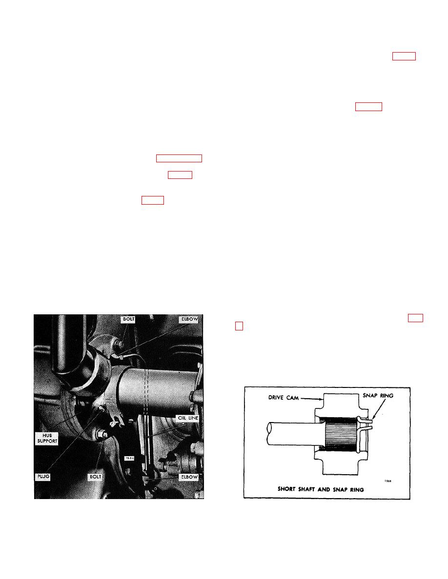
Remove the blower drive oil line, see Fig. 3.
and cavities are free of dirt.
3.
Straighten the ears on the lock washer (58) and
Replace the thrust washers if they are worn or scored.
loosen the drive gear hub nut (57), Fig. 5.
If the bearings are worn or scored excessively the drive
4.
Remove the blower drive support attaching bolts.
gear hub support or bearings will have to be replaced.
These bushing type bearings are diamond bored to an
5.
Loosen the blower drive support by tapping it
inside diameter of 1.6260" to 1.6265", after installation
lightly and withdraw the support from the cylinder block
in the hub.
rear end plate. Take care to prevent damage to the
blower drive gear teeth. Discard the gasket.
The clearance between the bearings and the hub is
.0010" to .0025" with new parts and a maximum of
Disassemble
Blower
Drive
Gear
and
Support
.0050" with used parts.
Assembly
The current bearing on the gear end protrudes .045" to
1.
Secure the blower drive gear and support
.055" above the surface of the face to facilitate the
assembly in a vise with soft jaws.
installation of the blower drive thrust washer (102) Fig.
.030" below the surface of the face of the support. Each
of the former bearings were flanged. Replacement
bearings must withstand a 2000 lb end load without
moving, also the bearing bores must be square with the
inner and outer faces of the support within .001" total
indicator reading.
Fig. 3. Blower Drive Gear and Support Assembly
Fig. 4. Bower Drive Shaft Mounting
Mounting
10-2-125


