
TM 5-3895-359-14&P
7. Stone the edge of all oil holes in the journal surfaces
smooth to provide a radius of approximately 3/32 ".
8. After grinding has been completed, inspect the
crankshaft by the magnetic particle method to determine
whether cracks have originated due to the grinding
operation.
9. Demagnetize the crankshaft.
10. Remove the plugs and clean the crankshaft and oil
passages thoroughly with fuel oil. Dry the shaft with
compressed air and reinstall the plugs.
Install Crankshaft
If a new crankshaft is to be installed, steam clean it to
remove the rust preventive, blow out the oil passages
with compressed air and install the plugs.
NOTE:
Fig. 8. New or Morco Remanufactured Crankshaft
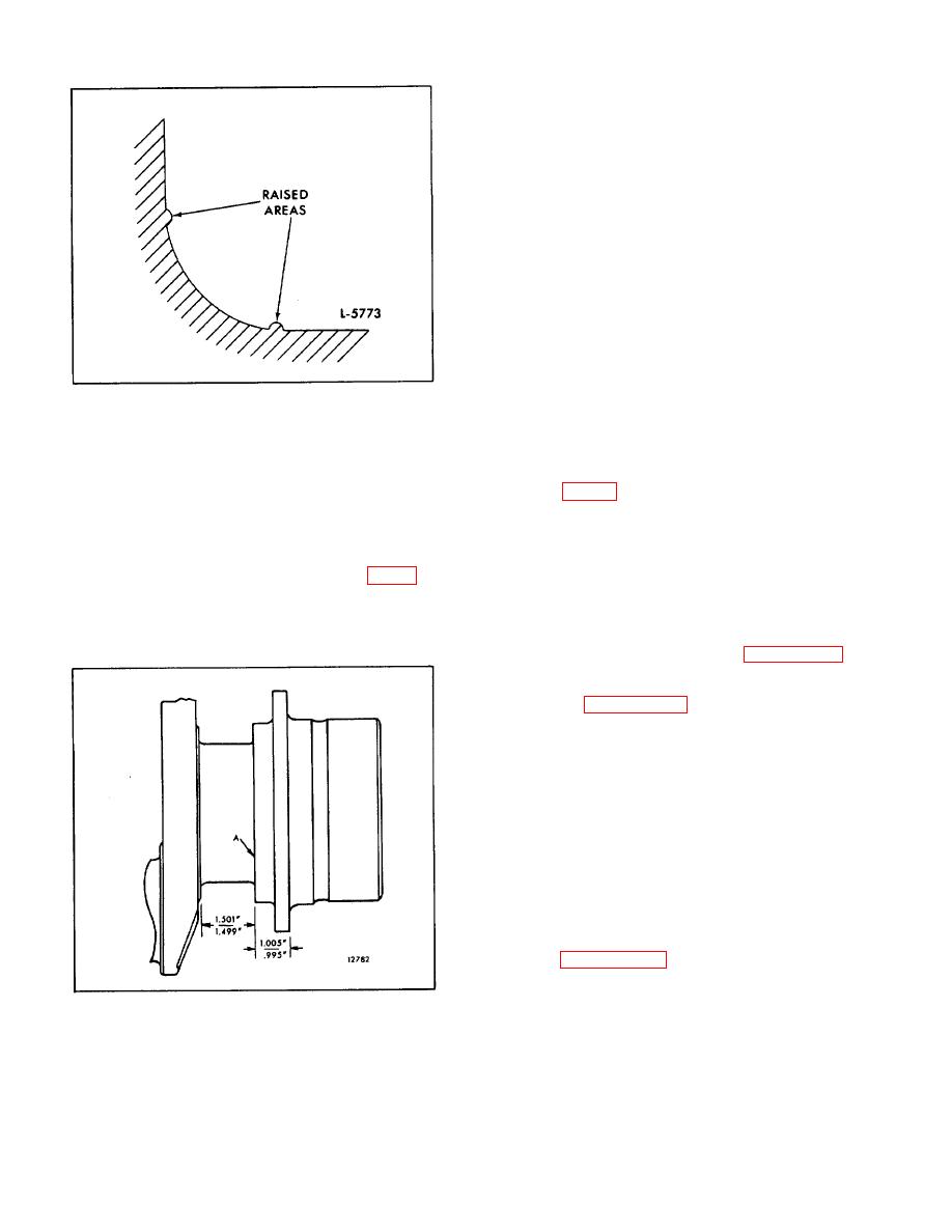
A new or remanufactured "Morco"
crankshaft receives a rolling process
often produces grinding cracks. Cool the crankshaft
in the fillet area for added strength.
while grinding, using coolant generously. Do not crowd
Oftentimes this leaves a slightly
the grinding wheel into the work.
raised area at each end of the fillet
5. Polish the ground surfaces to an 8-12 R.M.S. finish.
and must not be confused with
The reground journals will be subject to excessive wear
outside reground shafts that are left
unless polished smooth.
with a notch rather than a required
blend as outlined under Crankshaft
6. If the thrust surfaces of the crankshaft (Fig. 9) are
Grinding.
worn or grooved excessively, they must be reground
Then install the crankshaft as follows:
and polished. Care must be taken to leave a .130 " to
.160" radius between each thrust surface and the
1. Assemble the crankshaft timing gear (Page 10-2-
bearing journal.
123) and the oil pump drive gear (Page 10-5-10) on the
crankshaft.
2. Refer to Page 10-2-59 for main bearing details and
install the upper grooved main bearing shells in the
block. If the old bearing shells are to be used again,
install them in the same locations from which they were
removed.
NOTE:
When a new or reground crankshaft
is installed, ALL new main and
connecting rod (upper and lower)
bearing shells and new thrust
washers must also be installed.
3. Apply clean engine oil to all crankshaft journals and
install the crankshaft in place so that the timing marks
on the crankshaft timing gear and the idler gear match.
Refer to Page 10-2-104 for the correct method of timing
the gear train.
Fig. 9. Standard Dimensions at Crankshaft Thrust
4. Install the upper halves of the crankshaft thrust
Surfaces
washers on each side of the rear main bearing support
and the doweled lower halves on each side of the rear
main bearing cap. The grooved side of the thrust
washers must face toward the crankshaft thrust
surfaces.
10-2-53
