TM 5-3895-359-14&P
WATER MANIFOLD
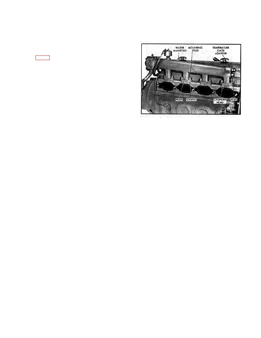
Cooling water, leaving the cylinder head through an
opening over each exhaust port, enters the water
manifold which is attached to the head with two nuts and
lock washers at each of the six water openings, as
shown in Fig. 1. A separate gasket is used at each
attaching flange between the manifold and the cylinder
head.
A gradually increasing area in the cast manifold from
the rear end terminates in either a uniform circular
section at the front where a seal and clamp connect the
manifold to the thermostat housing, or a mounting
flange to which the thermostat housing is attached by
means of bolts and lock washers.
Remove Water Manifold
Fig. 1 - Typical Water Manifold Mounting Industrial
The water manifold may be removed as follows:
Unit
1. Drain the cooling system to level necessary by
Install Water Manifold
opening the valve in the bottom of the fresh water pump
and the valve in the thermostat housing.
1. With new gaskets in place, lower the water manifold
down over the studs and secure it to the cylinder head
2. Loosen the bolts which secure the outlet elbow and
with two nuts and lock washer at each riser. Tighten the
the thermostat housing to the water manifold.
nuts to 2530 lb-ft (34-41 Nm) torque.
3. Remove the cooling water temperature gage adaptor
2. Install the temperature gage adaptor in the end of the
from the rear end of the water manifold.
manifold.
4. Remove the water manifold stud nuts and lock
3. Attach the thermostat housing and outlet elbow to the
washers and lift the manifold straight up off the studs.
water manifold with bolts and lock washers.
Remove the manifold to cylinder head gaskets.
4. Fill cooling system to proper level.
10-6-10


