
TM 5-3895-359-14&P
Revolve the pump shaft bearing slowly by hand.
NOTE:
Replace the shaft and bearing assembly and the seal
Do not mar the polished surface of
assembly.
the ceramic insert.
Inspect the ceramic insert for cracks, scratches and
3. Place the impeller assembly in a level position, with
bond to the impeller. If the insert is damaged, replace it
the ceramic insert up, in an oven preheated to 350
F
as follows:
(177 ) and bake it for one hour.
C
1. Bake the insert and impeller assembly at 500
F
NOTE:
(260C) for one hour. The insert can be removed easily
The face of the ceramic insert must
while the adhesive is hot. After removing the insert,
be square with the axis of the
clean the insert area on the impeller with sandpaper,
tapered bore within .004". The pump
wire brush or a buffing wheel to remove the old
shaft may be used as a mandrel for
adhesive, oxide, scale, etc.
inspection.
2. Examine the studs in the pump body. If it is
4. Remove the impeller from the oven and, after it has
necessary to replace a stud, use a good grade of sealant
cooled to room temperature, install it in the pump. Do
on the threads and drive the stud in to 6-8 lb-ft (8-11
not loosen the clamping bolt until the assembly cools.
Nm) torque.
Make sure the mating surfaces of the water seal and the
ceramic insert are free of dirt, metal particles and oil
Assemble Water Pump
film.
Refer to Figs.
5. Support the impeller end of the pump body on an
follows:
arbor press and insert the coupling end of the shaft and
bearing assembly into the pump body. Then press
1. Wet a clean cloth with a suitable solvent such as
against the outer race of the bearing until the bearing
alcohol and thoroughly clean the impeller insert area
contacts the shoulder in the pump body.
and the grooved side of a new ceramic insert. Then
wipe the parts with a clean, dry cloth.
NOTE:
When installing the shaft and bearing
2. Place the adhesive washer in the impeller bond area
assembly, it will not be necessary to
with the ceramic insert on top. The polished face of the
stake the end of the pump body.
ceramic insert should be visible to the assembler.
Clamp the insert and impeller together with a 3/8" bolt
6. With the surface of the pump seal clean and free
and nut and two smooth .125" thick washers. Tighten
from dirt and metallic particles, apply a thin coat of
the bolt to 10 lb-ft (14 Nm) torque.
liquid soap on the inside diameter of the rubber seal. To
reduce possible coolant leakage, apply a light coat of
non-hardening sealant on the outside diameter of a
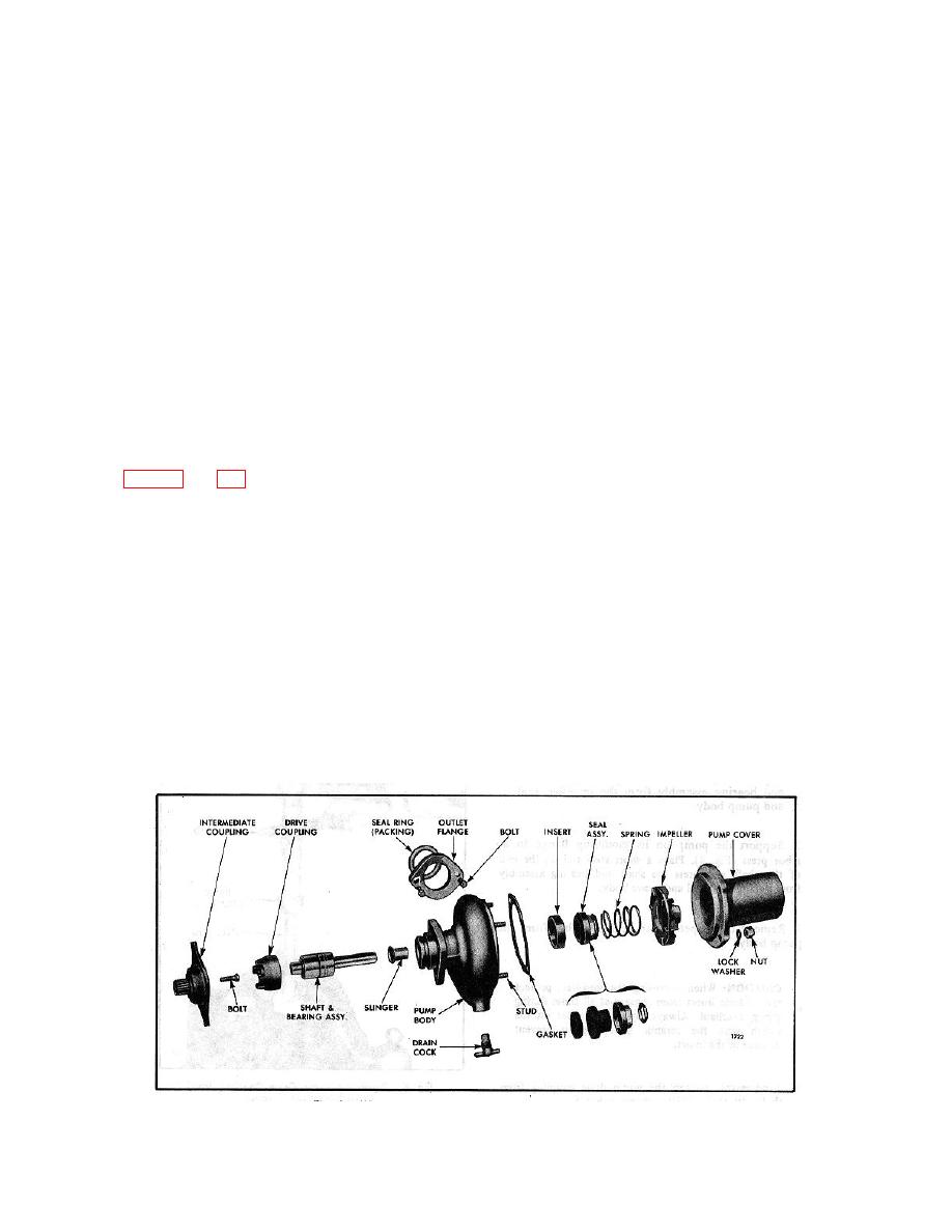
Fig. 6 - Water Pump Details and Relative Location of Parts
10-6-8
