TM 5-3895-359-14&P
10. Rotate the shaft by hand to be sure the rear face of
the impeller blades does not rub the pump body.
11. Place a new pump cover gasket against the bolting
flange of the pump body. Slide the pump cover over the
studs and secure it to the pump body with four lock
washers and nuts.
12. If previously removed, install the drain cock in the
pump body.
Install Water Pump
Refer to Fig. 2 and install the water pump on the engine
as follows:
1. Make sure the intermediate shaft coupling is secure.
If it was previously removed, insert the splined end of
the coupling into the mating splines in the blower rotor
shaft. Then draw the coupling in place with the 5/16"-24
x 1-1/2" bolt. Tighten the bolt to 15-19 lb-ft (20-26 Nm)
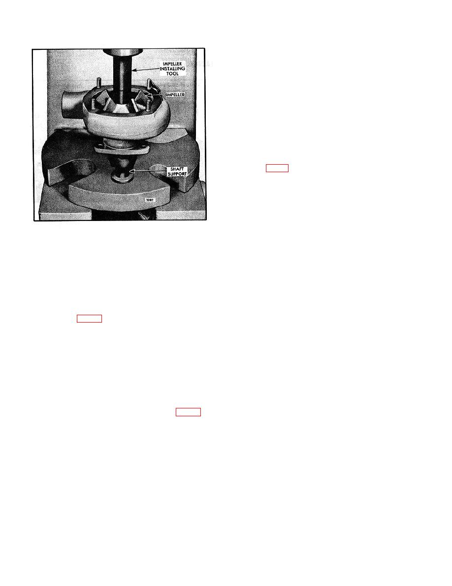
Fig. 7 - Installing Pump Impeller
2. Place the pump outlet flange over the pump outlet
new water seal. Press the seal assembly in place with a
with the flat side of the flange facing the pump body.
suitable sleeve until it seats firmly against the pump
Slip the packing ring over the pump outlet and next to
body. Then install the spring with the small end toward
the flange.
the seal.
3. Use a new gasket at the bolting flange and place the
7. Support the bearing end of the shaft on the bed of an
pump against the blower end plate cover so that the lugs
arbor press. Then press the impeller on the shaft using
on the drive coupling mesh with the lugs on the
tool J 22437 (Fig. 7). Do not press against the outer
intermediate shaft coupling. Secure the pump to the
race of the bearing. The distance between the end of
blower with the three bolts and seal washers.
the shaft and the face of the impeller hub is .031"-.033",
with the bearing held against the shoulder in the pump
4. Slide the pump outlet packing ring and packing
body.
flange against the cylinder block and secure the flange
with two bolts and lock washers.
8. Support the impeller end of the pump shaft on a
suitable arbor and press the coupling on the shaft. The
5. Slide the water pump inlet hose in place and secure
drive coupling must be flush with the end of the shaft.
it with the hose clamps.
Make sure the drive coupling is tight on the shaft.
6. Close the pump drain cock and fill the engine cooling
9. The pump includes a neoprene cover (Fig. 1) to
system.
allow coolant to drain, but still keep dust and dirt out of
the pump body at the weep hole. The neoprene cover
will stretch for removal or installation.
NOTE:
Be sure the tip of the cover is located
below the weep hole in the pump
body.
10-6-9


