
TM 5-3895-359-14&P
or scratches. Also check the surface which contacts the
injector bushing for scratches, scuff marks or other
damage. If necessary, lap this surface. A faulty sealing
surface at this point will result in high fuel consumption
and contamination of the lubricating oil. Replace any
loose injector body plugs or a loose dowel pin. Install
the proper number tag on a service replacement injector
body.
Inspect the injector plunger and bushing for scoring,
erosion, chipping or wear. Check for sharp edges on
that portion of the plunger which rides in the gear.
Remove any sharp edges with a 500 grit stone. Wash
the plunger after stoning it. Check the port holes in the
inner diameter of the bushing for cracks or chipping.
Slip the plunger into the bushing and check for free
movement. Replace the plunger and bushing as an
assembly if any of the above damage is noted, since
they are mated parts. Use new mated factory parts to
assure the best performance from the injector.
Injector plungers cannot be reworked to change the
output. Grinding will destroy the hardened case at the
helix and result in chipping and seizure or scoring of the
plunger.
Examine the spray tip seating surface of the injector nut
and spray tip for nicks, burrs, erosion or brinelling.
Reseat the surface or replace the nut or tip if it is
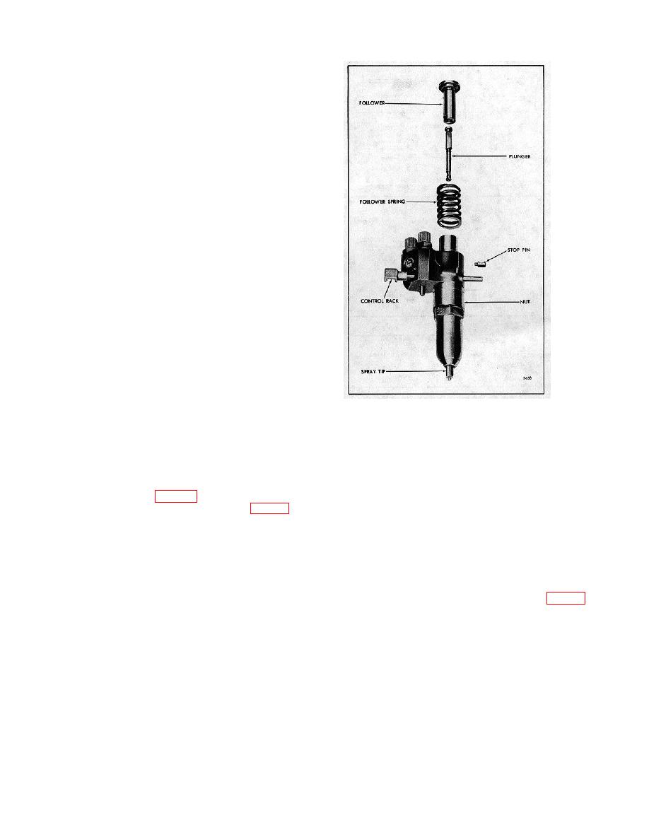
Fig. 37. Injector Plunger, Follower and Relative
severely damaged.
Location of Parts
The injector valve spring plays an important part in
stick 6 to 12 times, applying a light pressure with the
establishing the valve opening pressure of the injector
thumb and forefinger.
assembly. Replace a worn or broken spring.
NOTE:
Inspect the sealing surfaces of the injector parts
Be sure that no compound is
indicated by arrows in Fig. 31. Examine the sealing
accidentally placed on the lapped
surfaces with a magnifying glass as shown in Fig. 32 for
surfaces located higher up in the
even the slightest imperfections will prevent the injector
spray tip.
The slightest lapping
from operating properly. Check for burrs, nicks, erosion,
action on these surfaces can alter
cracks, chipping and excessive wear. Also check for
the near-perfect fit between the
enlarged orifices in the spray tip. Replace damaged or
needle valve and tip.
excessively worn parts. Check the minimum thickness
of the lapped parts as noted in Table 1.
Before reinstalling used injector parts, lap all of the
sealing surfaces indicated by the arrows in Fig. 31. It is
Examine the seating area of the needle valve for wear
also good practice to lightly lap the sealing surfaces of
or damage. Also examine the needle quill and its
new injector parts which may become burred or nicked
contact point with the valve spring seat. Replace
during handling.
damaged or excessively worn parts.
NOTE:
Examine the needle valve seat area in the spray tip for
The sealing surface of current spray
foreign material. The smallest particle of such material
tips is precision lapped by a new
can prevent the needle valve from seating properly.
process which leaves the surface
Polish the seat area with polishing stick J 22964. Coat
with a dull satin-like finish; the
only the tapered end of the stick with polishing
lapped surface on former spray tips
compound J 23038 and insert it directly into the center
was
of the spray tip until it bottoms. Rotate the
10-3-19
