
TM 5-3895-359-14&P
8. Remove the two bolts used temporarily to retain the
in the increased clamp direction to
flywheel, apply International Compound No. 2 as
prevent underclamping.
described above, then reinstall them.
12. Mount a dial indicator on the flywheel housing and
check the runout of the flywheel at the clutch contact
9. Use an accurately calibrated torque wrench and
face. The maximum allowable runout is .001 " total
tighten the bolts to 50 lb-ft (68 Nm) torque.
indicator reading per inch of radius (or .001mm per
millimeter of radius). The radius is measured from the
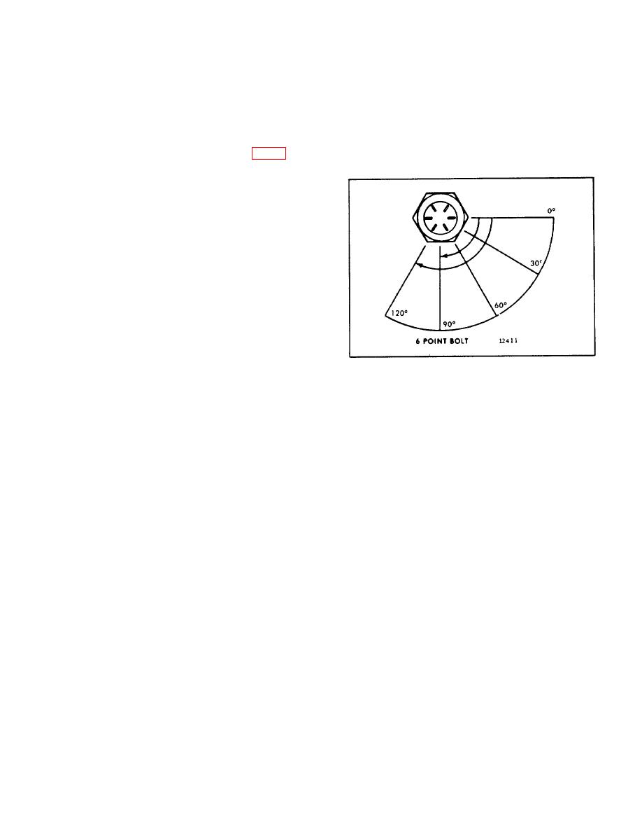
10. Turn the bolts an additional 90120 (Fig. 4) to
-
center of the flywheel to the outer edge of the clutch
obtain the required clamping.
contact face of the flywheel.
NOTE
Since
the
torque-turn
method
provides more consistent clamping
than the former method of flywheel
installation, bolt torque values
should be ignored.
IMPORTANT
When a clutch pilot bearing is
installed, index the flywheel bolts so
that the corners of the bolt heads do
not overlap the pilot bearing bore in
the flywheel. Thus, one of the flats
of each bolt head will be in line with
Fig. 4. Torque - Turn Limits
the bearing bore. Always rotate bolts
10-2-73
