
TM 5-3895-359-14&P
CRANKSHAFT PULLEY
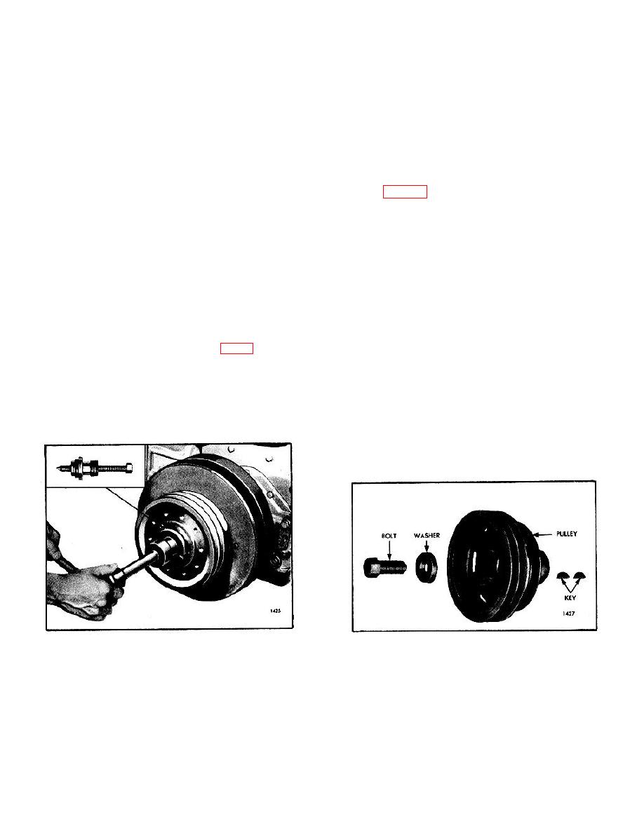
The crankshaft pulley incorporates a rubber insulator
crankshaft pulley. Check for failure of the rubber
between the pulley and the pulley hub for vibration
bushing by locking the crankshaft and applying pressure
dampening.
to the crankshaft pulley. If the pulley cannot be rotated,
the bushing is in satisfactory condition. If necessary,
The crankshaft pulley is keyed to the crankshaft and
replace the rubber bushing.
secured with a special washer and bolt.
Install Crankshaft Pulley
The new crankshaft bolts are now lubrite coated to
prevent possible damage (galling) to the bolt threads
Refer to Fig.
and to increase the clamp load to the front end stack up
follows:
(crankshaft pulley, vibration damper, etc). Also the new
washer (retainer) is now case hardened.
1. Place the Woodruff keys in the key slots in the front
end of the crankshaft, if they were removed.
The new bolts and washer can be identified by their
2. Slide the pulley over the end of the crankshaft.
black color. The former bolts and washer are a steel
3. Place the washer on the bolt and thread the bolt into
(gray) color.
the end of the crankshaft, drawing the pulley tight
against the oil seal spacer. The pulley must be drawn
Remove Crankshaft Pulley
tight against the outer cone.
1. Remove drive line adapter plate by removing the five
4. Tighten the crankshaft pulley retaining bolt as
capscrews from crankshaft pulley.
follows:
2. Remove the bolt and washer.
3. Use puller J 5356 as illustrated in Fig. 1. Clean the
a. Tighten the bolt to 180 lb-ft (244 Nm) torque.
threads of the tool and pulley. Screw the 2 1/2"-16
b. Strike the end of the bolt a sharp blow with a 2 or 3
thread into the pulley hub as far as possible with the
lb. lead hammer.
center screw backed off. Then force the pulley off the
c. Tighten the bolt to 300 lb-ft (407 Nm) torque and
crankshaft by turning the center screw in.
strike the bolt again.
d. Tighten the bolt to 290-310 lb-ft (393-421 Nm)
torque.
Inspection
NOTE
Do not strike the bolt after final
torque has been applied.
Fig. 1. Removing Rubber Mounted Pulley from
Fig. 2. Crankshaft Pulley Details
Crankshaft using Tool J 5356
The appearance of the rubber bushing does not
determine the condition of a rubber mounted
10-2-69
