
TM 5-3895-342-34
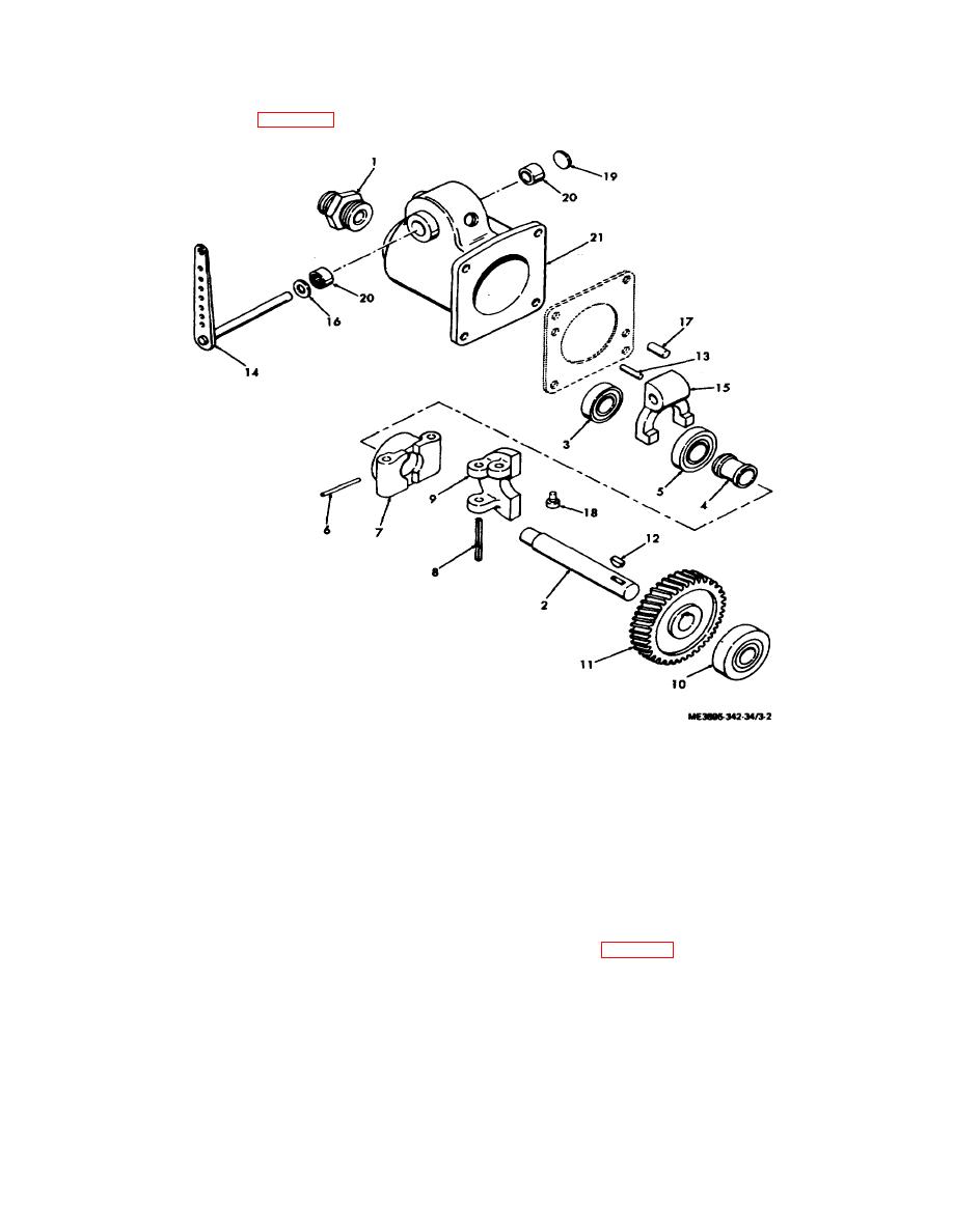
b. Disassembly. Disassemble the governor in
numerical sequence shown in figure 3-2.
1.
Adapter, tachometer
8. Pin, spring
15.
Governor yoke
2.
Drive haft
9. Governor flyweight
16.
Packing, preformed
3.
Bering
10. Bearing
17.
Pin
4.
Thrust sleeve
11. Governor gear
18.
Pin, straight headed
5.
Bearing
12. Key, woodruff, No. 404
19.
Plug, expansion
6.
Pin, tapered
13. Pin, tapered, No. 0 x in.
20.
Needle bearing
7.
Flyweight hub
14. Cross-shaft and lever
21.
Governor body
Figure 3-2. Governor, exploded view.
c.
Cleaning, Inspection and Repair.
e. Installation. Install the governor in reverse of
(1) Clean all parts with cleaning solvent.
instructions in figure 3-1.
f.
Adjustment.
(2) Inspect all parts for wear or damage.
Repair or replace worn or damaged parts.
(1) Disconnect the control rod ball joint from
d. Reassembly. Reassemble the governor in
the governor lever, and then pus h the rod assembly
toward the carburetor as far as it will go. The governor
reverse of numerical sequence as illustrated in figure 3-
lever would then be moved as far as
2.
3-2
