
TM 5-3895-342-12
Section XIII. CLUTCH ASSEMBLY
4-46. General
b. Release the clutch by pushing the clutch
The clutch is housed in a power transfer case on the
engine crankshaft. It is a wet-type disk clutch which
lever toward the engine.
is operated by a clutch lever and yoke mechanism.
c. Turn the engine over until the clutch
4-47. Clutch Adjustment
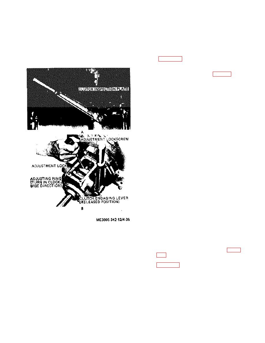
adjustment lock is visible through the inspection
opening (fig. 4-35).
Loosen the adjustment
a. Remove the clutch inspection plate (fig. 4-
lockscrew one full turn.
35).
d. While keeping the engine crankshaft from
turning, turn the notched adjusting ring fig. 4-35) one
notch at a time in a clockwise direction, until a very
firm pressure is required to engage the clutch with
the lever. The clutch will snap into engaged position,
when it is correctly adjusted.
e. Securely tighten adjustment lockscrew.
f. Install inspection plate being sure that the
gasket fits properly and is not broken.
Figure 4-35. Clutch adjustment.
Section XIV. WATER SYSTEM
4-48. General
4-49. Pump Belt
The water system consists of an automatic siphon
cut-off type tank, a water pump, and a three-way
a. Removal.
valve. The amount of water discharged into the
(1) Remove belt guard as instructed on figure
drum is pre-determined by the operator by setting the
indicator lever on the graduated quadrant. This lever
(2) Remove the pump belt as instructed on
moves the siphon head up or down to regulate the
exact amount of mixing water desired.
4-21
