TM 5-3895-342-12
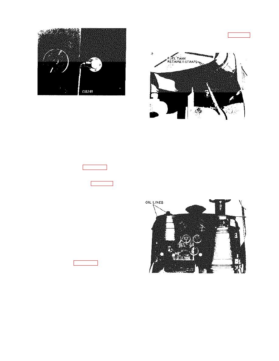
(2) Remove fuel level sending unit (para 4-31).
(3) Remove fuel tank as instructed on figure 4-
28.
1. DISCONNECT WIRES.
2.
REMOVE REMAINING SCREWS (4) AND
SENDING UNIT.
ME 3895-342-12/4-27 C1
REMOVE CAPSCREWS, NUTS AND WASHERS
Figure 4-27. Fuel level sending unit removal.
FROM FUEL TANK RETAINER STRAPS AND
b. Cleaning and Inspection.
(1) Clean the fuel level sending unit with a REMOVE FUEL TANK.
ME 3895-342-12/4-28 C1
cleaning solvent.
Figure 4-28. Fuel tank removal.
(2) Inspect the fuel level sending unit for
damage. Replace a damaged fuel level
b. Cleaning and Inspection.
sending unit.
(1) Clean all parts with a cleaning solvent.
c. Installation. Install the fuel level sending unit
(2) Inspect the fuel tank for leaks and damage.
in reverse of instructions on figure 4-27.
Replace leaking or damaged fuel tank.
4-32. Fuel Tank
c. Installation. Install the fuel tank in reverse of
a. Removal.
instructions in a above.
(1) Remove fuel strainer (para 4-29).
Section XI. LUBRICATION SYSTEM
4-33. General
The lubrication system consists of an oil pump, oil
filter, and an oil pressure relief valve. The pump
supplies oil to four nozzles which direct oil streams
against fins on the connecting rod caps. Part of the
oil enters the rod bearing through holes in the rod,
and the balance of the oil forms a spray or mist which
lubricates and cylinders and other internal parts of the
engine. An external oil line from the oil header tube
in the crankcase lubricates the governor and the gear
train.
4-34. Oil Filter
a. Removal. Remove the oil filter. lines. And
fittings as instructed on figure 4-29.
b. Remove the cover thru-bolt and
disassemble oil filter. Discard element and gasket.
1. DISCONNECT OIL LINES.
2. REMOVE CAPSCREWS (4), WASHERS (4),
LOCKWASHERS (4), NUTS (4) AND OIL FILTER.
ME 3895-342-12/4-29 C1
Figure 4-29. Oil filter removal.
4-18
Change 1


