
TM 5-3895-369-14
NOTES:
1.
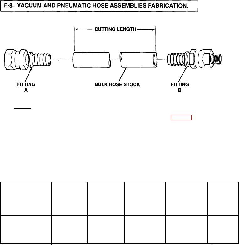
OBTAIN ALL COMPONENTS REQUIRED TO FABRICATE DESIRED HOSE ASSEMBLY (TABLE F-l).
2.
USE A FINE TOOTHED HACKSAW OR SUITABLE CUTTING DEVICE, AND CUT HOSE TO INDICATED LENGTH.
3.
PLACE FITTING A IN VISE.
4.
SLIDE AND TURN HOSE ON FITTING A UNTIL HOSE BOTTOMS AGAINST FITTING. BACK OFF 1/4 TURN.
5.
PLACE FITTING B IN VISE.
6.
SLIDE AND TURN HOSE ON FITTING B UNTIL HOSE BOTTOMS AGAINST FITTING. BACK OFF 1/4 TURN.
Figure F-7. Vacuum and Pneumatic Hoses.
Table F-1. Vacuum and Pneumatic Hose Assemblies and Fittings.
Hose Assembly
Bulk Hose
Cutoff Length
Fitting
Fitting
Ferrule
Manufacturer's
P a r t Number
A
I n c h e s (mm)
B
C
P a r t Number
4LOLA-2FP-2MP-80
4LOLA
274-0402
80(2032)
272-0402
N/A
4LOLA-2FP-2MP-27
4LOLA
274-0402
272-0402
N/A
27 (686)
F-7