
TM 5-3895-369-14
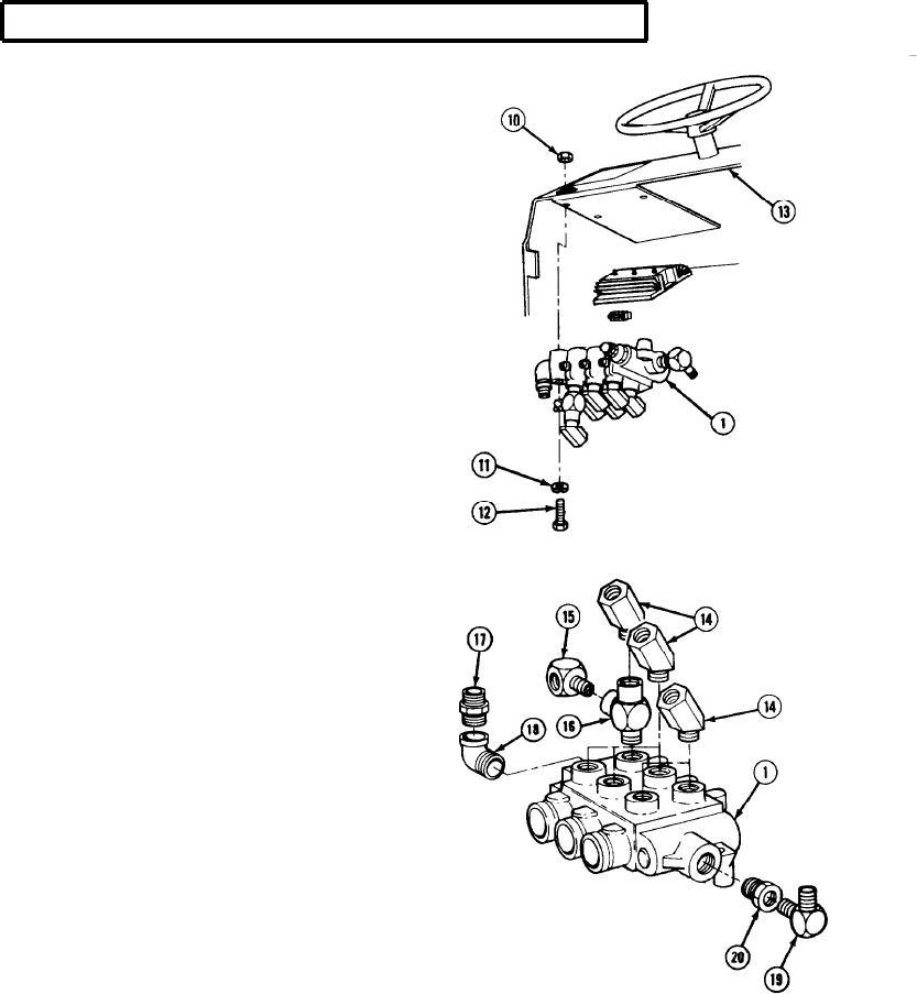
5-83. VALVE BANK ASSEMBLY REPLACEMENT (CONT).
(5) Remove two nuts (10), three
lockwashers (11), screws (12), and valve
bank (1) from dash (13). Discard
NOTE
Note position of fittings before removal for
proper installation.
(6) Place bank valve (1) in vise and remove six
elbows (14) from valve bank (1). Cap ports
to prevent contamination.
(7) Remove elbow (15) and tee (16) from valve
bank (1). Cap port.
(8) Remove nipple (17) and elbow (18) from
valve bank (1).
(9) Remove elbow (19) and adaptor (20) from
valve bank (1).
5-494