
TM 5-3895-369-14
Compressed air used for cleaning purposes must not exceed 30 psi (207 kPa). Use only with effective
chip guarding and personal protective equipment (goggles/shield, gloves, etc).
(2) Dry all parts, except bearing cups, with compressed air. Let bearings air dry.
(3) Check all parts for damage.
(4) Replace damaged parts.
Assembly.
c.
NOTE
This procedure is the same for both ends of
the clutch drive shaft.
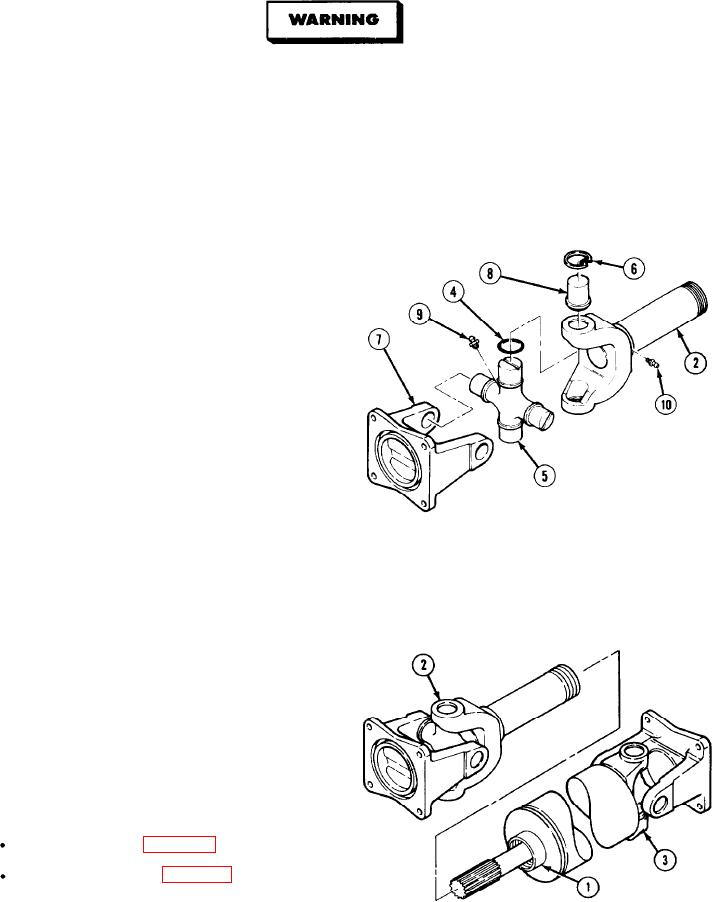
(1) Install grease fitting (10) in slip yoke (2)
(2) Install grease fitting (9) and position four
seals (4) on universal joint (5).
(3) Position universal joint (5), flange yoke (7),
and slip yoke (2).
CAUTION.GPH;12p10;6 P10;TIFF
Be careful when installing bearing cups.
Needle bearings may fall out and become
damaged or lost.
(4) Apply grease in insides of four bearing cups (8) and install slip yoke (2) and flange yoke (7) over ends of
universal joint.
(5) Install four clips (6) and slide grease seals (4) into place.
(6) Align matchmarks and install slip yoke (2) on drive shaft (3).
(7) Install seal (3).
NOTE
Follow-on Maintenance:
Install drive shaft (para 4-102)
Lubricate drive shaft (figure 3-1).
END OF TASK
5-363