TM 5-3895-359-14&P
4. If necessary, bore the cylinder block as follows:
the hone and makes it difficult to feel the high
a. Each bore in a used block must not be out-of-
spots. Therefore, use a light cut with frequent
stone adjustments.
round or tapered more than .002 ". If the
average block bore is over 4.6285," the block
e. Wash the cylinder block thoroughly after the
should be bored oversize (refer to Tables 1 and
honing operation is completed.
2).
2. The cylinder liner is alternately expanding and
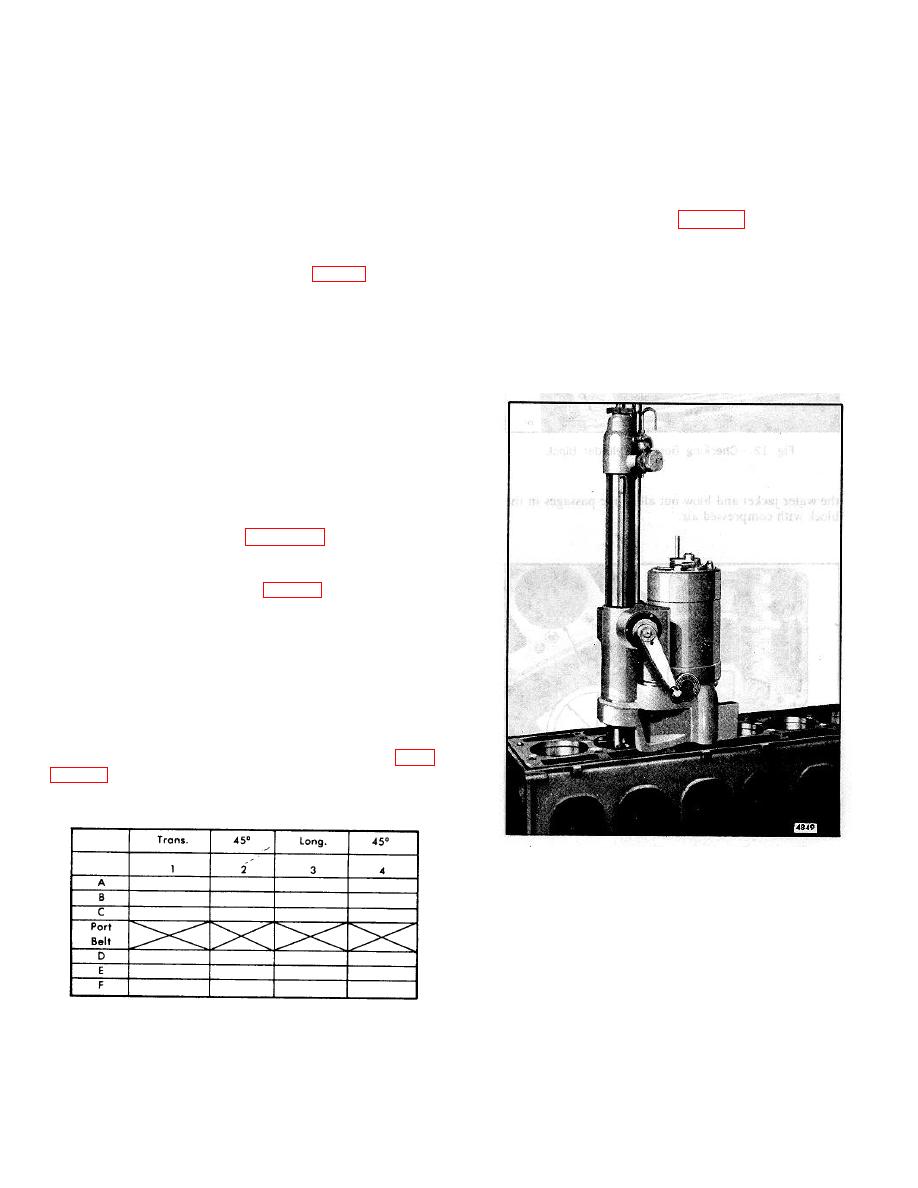
b. A typical commercially available portable boring
contracting, during engine operation.
due to
bar is illustrated in Fig. 15. Instructions on
temperature variations. This may result in irregularities
correct use of the boring bar are provided by the
in the block bores (out-of-round and taper), the effects
manufacturer.
of which will be seen as high pressure areas on the
outside diameter of the cylinder liner (Fig. 11). A slight
c. After boring the block for an oversize cylinder
increase in block bore size is normal with high mileage
liner, check the bore finish to be sure it is
or long period: o)I engine operation.
smooth (120 RMS). Heat transfer from the
cylinder liner to the block will be adversely
a. Visually check the contact area as revealed by
affected if the block bore isn't smooth.
the honed surface. There must not be any low
spots which are larger in area than a half dollar.
d. Wash the block thoroughly after the boring
operation.
b. Measure the entire bore of each cylinder with
cylinder bore gage J 5347-01 (Fig. 12) which
has a dial indicator calibrated in .0001 "
increments. The standard block bore is 4.6260"
to 4.6275." Place the bore gage in the master
ring gage J 8386-01 which has an I.D. of
4.6270" and set the dial to zero.
Take
measurements on the cleaned-up surface only
at positions A, B, C, D, E and F in the bore on
axes 45 apart (Fig.
Read the
measurements from the zero mark on the gage.
The readings may be recorded on a form similar
to the one illustrated in Fig. 14.
NOTE: Dial bore gage setting master
tool J 23059-01 may be used in place of
the master ring gage.
3. The liner-to-block clearance with new parts is zero to
.0015." With used parts, the maximum clearance is
.0025." After measuring the bores, measure the outside
diameter of the cylinder liners (Page 10-2-94). Then
determine the block-to-liner clearances (refer to Page
be necessary to bore the block for oversize cylinder
liners.
Fig. 15. Boring Cylinder Block with Portable Boring
Bar
Fig. 14. Block Bore Measurement Record Form
10-2-10


