
TM 5-3895-342-34
Note. Screw a into one o the camshaft gear
plunger are in place in the end of the camshaft, a s they
hold the camshaft in position end-wise.
mounting holes in the front camshaft journal. Turn on
engine its side then move each valve lifter assembly into
the valve chamber free of the camshaft. Remove the
3-19.
Cylinder Blocks and Crankcase
camshaft from the crankcase.
a. Removal
b. Cleaning, Inspection and Repair.
(1) Remove the camshaft and valve lifters
(1) Clean all parts with cleaning solvent.
(2) Inspect all parts for wear and damage.
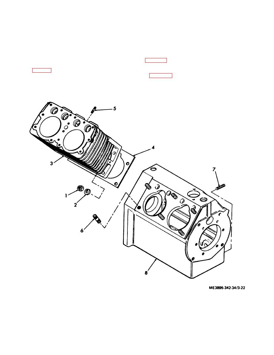
(2) Remove the cylinder block and gaskets
Refer to table 1-1 for wear limits and dimensions. Repair
from the crankcase in numeral sequence as illustrated
or replace worn or damaged parts.
in figure 3-22.
c. Installation. Install the camshaft and valve
lifters in reverse of instructions in subparagraph a above.
Note. Tag each cylinder block so that it will be
When reinstalling, be sure the spring
and
installed on the same side of the crankcase.
1.
Nut, hex, 7/16-20
5.
Stud, 3/8-16-24 2 in.
2.
Washer, Lock , 7/16 in.
6.
Stud, 7/6-14-20 x 2 in.
3.
Cylinder Block
7.
Stud, 5/16-18-24 x1 in.
4.
Gasket
8.
Crankcase
Figure 3-22. Cylinder block and crankcase assemblies, exploded view.
3-26
