
* TM 5-3895-342-34
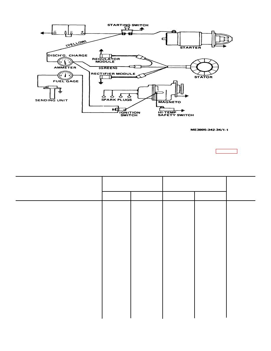
Figure 1-1. Wiring diagram.
b. Engine Repair and Rebuild Standard. Table 1-
c. Nut and Bolt Torque Data. Table 1-2 provides
1 lists manufacturer's sizes, tolerances and maximum
nut and bolt torque data.
allowable wear and clearance.
Table 1-1. Engine Repair and Rebuild Data
Manufacturer's dimensions
Maximum
Component
and tolerances in inches
Desired clearance
allowable
wear and
Minimum
Maximum
Minimum
Maximum
clearance
Camshaft
1.8725
1.8730
0.002
No. I Journal
1.8725
1.8730
0.002
No. 2 Journal
1.2475
1.2480
0.002
Camshaft bores
No. I Journal
1.875
1.876
0.002
No. 2 Journal
1.250
1.251
0.002
Clearance between camshaft and bore
0.002
0.0035
Connecting Rod
Id of installed bushing (crankcase end)
1.8115
1.8125
Clearance between connecting rod
bushing and crankshaft.
0.0019
0.0025
0.003
Side clearance between connecting
rod bushing and crankshaft.
0.004
0.011
0.005
Maximum out-of-round of bearing
crankshaft end).
0.0005
Id of piston end
0.9125
0.9130
Id of installed bushing (piston end)
0.8594
0.8597
0.001
Interference of bushing to id of rod
0.0025
0.0055
1-2
