TM 5-3895-342-34
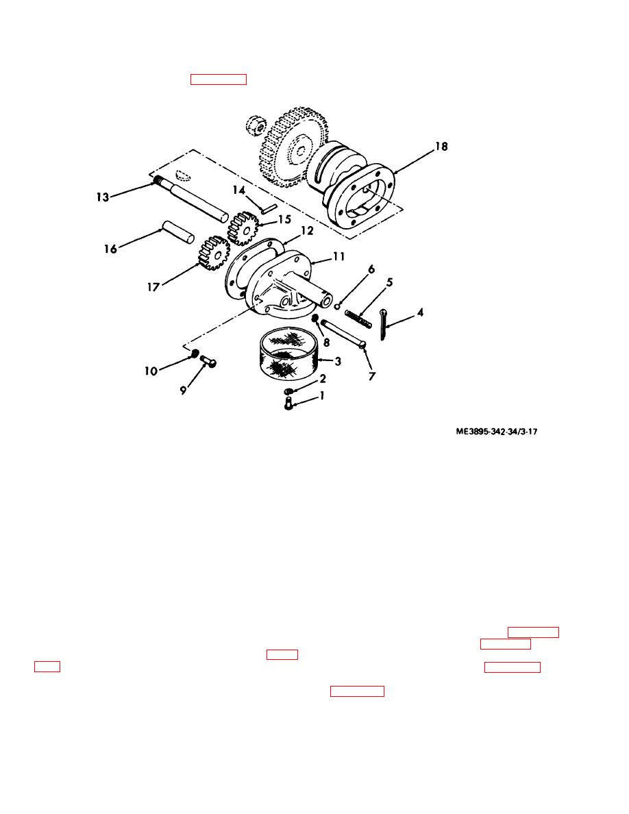
b. Disassembly. Disassemble the oil pump in
numeral sequence as illustrated in figure 3-17.
1.
Screw, Machine, No. 10-32 x 3/8 in.
10.
Washer, Lock, No. 10
2.
Washer, Lock, No. 10
11.
Oil Pump Cover
3.
Oil Pump Strainer
12.
Gasket
4.
Pin, Cotter, 1/8 x 1 in.
13.
Oil Pump Shaft
5.
Spring, Helical Compression
14.
Pin, straight headless, 1/8 x 3/4 in.
6.
Ball Bearing, 1/4 dia.
15.
Drive gear
7.
Screw, Machine, No. 10-32 x 1/4 in.
16.
Idler gear pi
8.
Washer, Lock, No. 10
17.
Idler gear
9.
Screw, Machine, No. 10-32 x I/2 in.
18.
Oil pump body
Figure 3-17. Oil pump, exploded view.
c.
Cleaning, Inspection and Repair.
3-16. Baffle Plates, Connecting Rod, and Piston
(1) Clean all parts with a cleaning solvent.
Assemblies
(2) Inspect all parts for wear and damage.
a. Removal.
Repair or replace worn or damaged parts.
(1) Remove cylinder heads (para 3-10).
d. Reassembly. Reassemble the oil pump in
(2) Remove oil pump (para 3-15).
reverse of the numerical sequence as illustrated in figure
(3) Remove the bearing caps, bearings, and
piston assemblies as instructed in figure 3-18.
e. Installation. Install the oil pump in reverse of
(4) Remove both baffle plates instructed in
the instructions in subparagraph a above.
3-21


