TM 5-3895-369-14
(c)
(d)
(e)
(f)
(g)
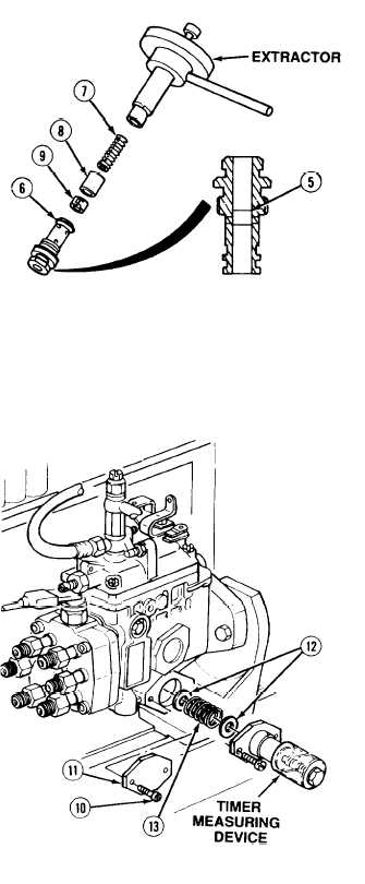
Using an extractor, disassemble control
valve (6) and remove spring (7), piston
(8) and spring ring (9).
Push plug (5) up to top of control
valve (6).
Install spring ring (9), piston (8), and
spring (7) in control valve (6).
Install control valve (6). Tighten
control valve 173 to 259 lb-in.
(20 - 29 N•m).
Measure pump chamber pressure at
speed indicated in calibration data. If
measurement is below limits, install
adjusting device and push in plug (5) in
control valve (6). Remove adjusting
device. If measurement is within limits,
go to step (4).
(4)
Adjust timer stroke as follows:
(a)
(b)
(c)
(d)
(e)
(f)
(g)
Remove two screws (10) and right
access cover (11) and install timer
measuring device with two screws.
Rotate injection pump at speed
specified in calibration data and check
timer strokes. If measurement is within
limits, go to step (6).
If measurement is not within limits,
remove two screws, timer measuring
device, two shims (12) and spring (13).
Install spring (13), two correct size
shims (12), timer measuring device, and
two screws.
Rotate injection pump and recheck
timer stroke for correct measurement.
If measurement is not within limits,
repeat steps (c) and (d). If
measurement is correct go to step (f).
Remove measuring device and install
right access cover (11) with two screws
(10). Tighten screws 60 to 86 lb-in.
(7 - 10 N•m).
Repeat step (2).
5-267


