TM 5-3895-369-14
(2)
Adjust full-load injection as follows:
(a)
(b)
(c)
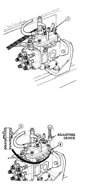
Set control lever (2) in maximum speed
position and check that governor
operates at speed specified in
calibration data. If speed is within
limits, go to step (d). If speed is not
within limits, do steps (1) to (4), (11).
(17), (22) to (26), (29, (30), and (32) of
a. Disassembly to remove governor
lever assembly.
Do steps (27), (31), (35), (37) to (40),
(47), (48), (54), (59), (65), and (66)
of c. Assembly to install governor
lever assembly.
Repeat step (a).
NOTE
Ensure to tighten nut (3) before each
reading.
(d)
Measure injection quantity at speed
specified in calibration data. If quantity
is within limits, go to step (3). If
quantity is not within limits, loosen nut
(3) and adjust full-load adjusting screw
(4). Tighten nut (3) 52 to 78 lb-in (6 - 9
N•m) and measure injection quantity
again to ensure correct quantity.
(3)
Adjust supply pressure as follows:
(a)
Measure pump chamber pressure at
speed indicated in calibration data. If
pressure is within limits go to step (4).
If pressure is below limits, install
adjusting device and push in plug (5) in
control valve (6). Remove adjusting
device.
(b)
If measurement is above limits, remove
control valve (6) and perform all
following steps.
5-266


