
TM 5-3895-369-14
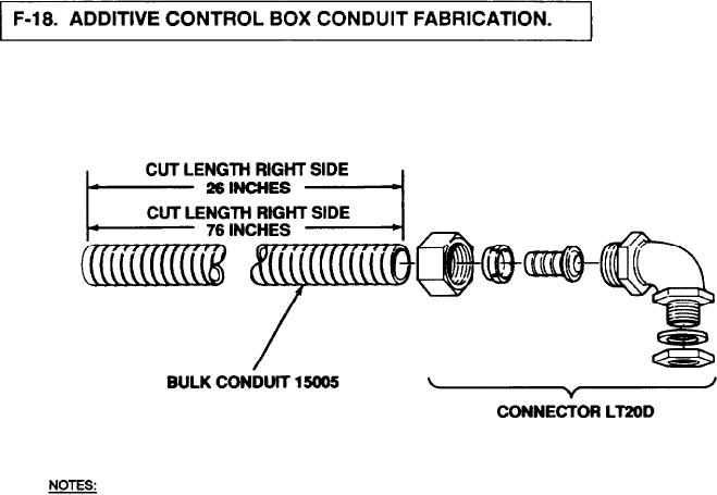
Two lengths of conduit are connected to the additive system control box. A 26 in. (660 mm) length is connected to the
left side of the control box, and a 76 in. (1930 mm) length is connected to the right side of the control box. Both of
these conduits are fabricated the same way. The instructions listed below apply to the fabrication of both conduits.
1.
OBTAIN ENOUGH BULK CONDUIT, PN 15005, TO FABRICATE CONDUIT TO DESIRED LENGTH.
2.
USE A FINE TOOTHED HACKSAW OR SUITABLE CUTTING DEVICE, AND CUT CONDUIT TO INDICATED LENGTH.
3.
INSTALL ONE CONNECTOR, PN LT20D, ON ONE END OF CONDUIT.
Figure F-17. Additive Control Box Conduit,
F-16