
TM 5-3895-369-14
5-89. PUMP FRAME REPLACEMENT.
This task covers:
b. Installation
a. Removal
INITIAL SETUP
Personnel Required
Tools
MOS62B, Construction equipment repairer (2)
Tool kit, general mechanic's: equipment
maintenance and repair
Equipment Condition
TM or Para
Condition Description
MaterialslParts
Additive pump assembly
Lockwasher (6)
removed.
Additive system motor
removed.
a.
Removal.
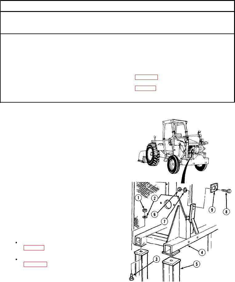
(1) Remove four nuts (1) lockwashers (2),
screws (3) and pump frame (4) from vehicle
frame (5). Discard lo&washers.
(2) Remove two nuts (6), lockwashers (7),
screws (8), and mounting block (9) from
pump frame (4). Discard lo&washers.
b. Installation.
(1) Install mounting block (9) on pump
frame (4) with two screws (8)
lo&washers (7), and nuts (6).
(2) Install pump frame (4) on vehicle frame (5)
with four screws (3). lockwashers (2), and
nuts (1).
NOTE
Follow-on maintenance:
Install additive system motor
Install additive pump assembly
END OF TASK
5-525