
TM 5-3895-359-14&P
TRAVEL SPEED UNIT
proper integration of the voltage signals for overall
The travel speed unit, figure6, consists of a pneumatic
system accuracy.
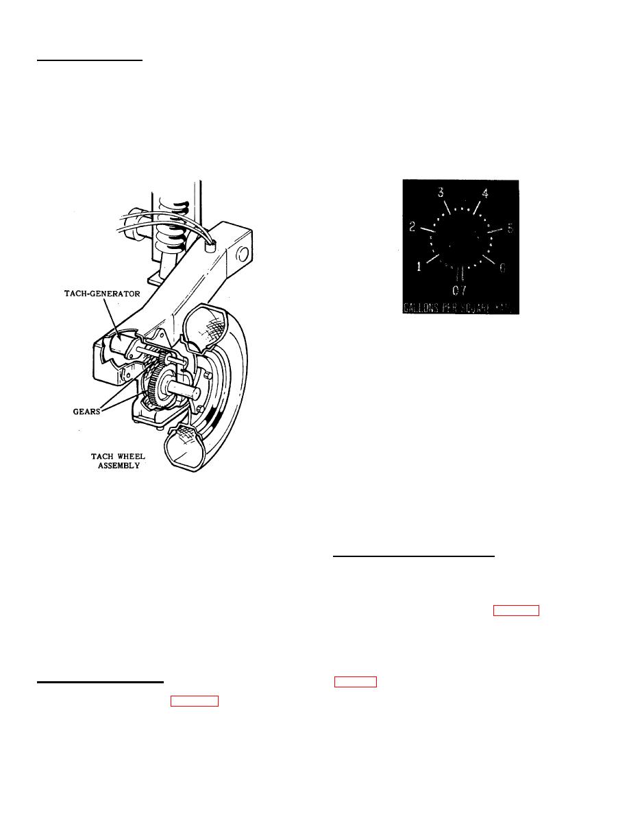
This calibration is effected by
tire and wheel that is automatically lowered to the
removing the control knob on the front of the V.P.I.
ground when the spray bar valves are opened. The
panel with a '4'" allen wrench. On the back of the V.P.I.
wheel drives a tach-generator through an enclosed gear
panel, connect an ohmmeter to posts #3 and #5 on the
box which generates a voltage proportionate to the
gallons per square yard potentiometer and rotate the
travel speed of the Pulvi-Mixer. If the tach-generator
shaft from a high ohm setting counterclockwise until an
leads have been removed, check that the polarity is
ohmmeter reading of one (1) ohm is reached. This
correct for the direction of travel in order to get an
operation should
indicator reading.
FIGURE 7
be repeated several times as there is no positive stop on
this potentiometer, only a "dead band." After the one (1)
ohm position has been determined, very carefully
replace the knob on the shaft with the pointer directed at
zero ("0") on the gallons per square yard legend plate.
Tighten the socket head set screw making sure #1, that
the one (1) ohm reading is repeatable with the pointer
directed at zero ("0") and #2, that the locking ring, when
turned clockwise holds the pointer securely at a
predetermined position.
FIGURE 6
The above operation may have to be repeated as it can
be quite delicate, however it is essential that it be done
This voltage is transmitted to the travel speed indicator
correctly.
mounted on the V.P.I. panel. The travel speed unit is
easily calibrated by measuring a suitable distance (50 ft.
PROPORTIONING SYSTEM UNIT
or 100 ft.) and timing the machine over the measured
distance maintaining a constant forward speed and
The proportioning system unit (performance meter) is
checking the rate against the indicator reading. With the
the last indicator to be adjusted in this sequence.
travel speed indicator pointer at 100 f.p.m. for example,
Before starting this adjustment procedure, check to see
the machine should traverse this distance (100 ft.) in
if the performance meter needle, figure 8, is reading
one minute. If it does not, adjust the tach wheel
zero ("0") in a rest or "no-power" position. If it is not,
potentiometer on the back of the V.P.I. panel until the
adjust the needle by slightly turning the adjusting screw
travel speed indicator reads correctly for the timed
near the bottom on the face of the meter. The
distance.
adjustment is accomplished by first selecting an
application rate from the application reference chart
APPLICATION RATE UNIT
the pointer with the locking ring.
The application rate unit, figure 7, consists of an
extremely accurate potentiometer that must be correctly
adjusted in order to signal the proportioning system the
13-4
