TM 5-3895-359-14&P
CALIBRATING THE V.P.I. SYSTEM-
totalizer will provide a gallons per minute flow rate and
METER RECORDING UNIT
the corresponding voltage output of the meter
tachgenerator. If the air method is used for checking
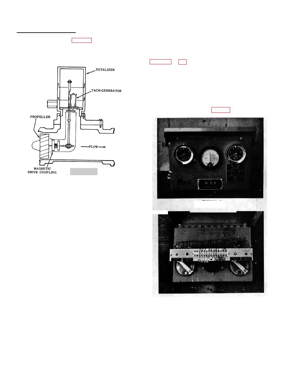
The meter recording unit, figure 2, is the basic unit of
the meter flow rate, do not rotate the propeller too fast.
the V.P.I. system and the accuracy of the total system
A flow rate of 200-400 gallons per minute is a good rate
depends largely upon the accuracy of the recording
at which to check the tach-generator voltage output.
totalizer head on the meter. This is calibrated to within
2%.
a specific flow rate, the gallons per minute indicator on
the V.P.I. panel may now be calibrated. Remove the
face bolts holding the V.P.I. panel in place and fold the
panel down so that the terminal block is accessible.
Remove the leads #3 and #8 (from the meter
tachgenerator) from the terminal block. Substitute an
adjustable external D.C. voltage source to terminals #3
and #8 of the same magnitude previously determined
for the given flow rate. Refer figure 5.
FIGURE 2
In operation, the meter propeller is rotated by the liquid
flow pressure passing through the line into which the
meter propeller is inserted. The propeller drives a worm
gear train through a magnetic coupling then directly to
FIGURE 3
the recording totalizer which records the total gallons
having passed through the meter. A tach-generator
connected to the basic gear train produces a voltage
signal proportionate to the liquid flow which is relayed to
the instrument panel where it indicates the flow in
gallons per minute.
In checking out and calibrating the meter recording unit,
it is best to pump a liquid through the meter, time the
flow and check it against the totalizer, simultaneously
checking the voltage output of the meter tach-generator.
This will determine the rate of flow and corresponding
voltage output under these specific conditions. The
voltage will be used later to calibrate the "gallons per
minute" indicator. If it is impractical to actually pump a
liquid thru the system, the meter body assembly
complete with the propeller may be removed from the
system and the flow rate determined by the following
FIGURE 4
method: Place the meter body assembly on a bench so
Adjust the meter tach-generator potentiometer so that
that the propeller will rotate freely, and with the meter
the gallons per minute indicator corresponds to the
mounting flange in a horizontal plane. If the meter is
same flow rate as determined by the timed totalizer
tipped excessively, oil will be lost from the lower gear
measurement.
The meter recording unit is now
train. A Type "A" transmission fluid must be added to
calibrated.
replace the lost oil. Direct an air hose with regulating
valve so
that it will rotate the propeller at a constant low speed.
This simulation of flow, timed and checked against the
13-2


