
TM 5-3895-359-14&P
Carburetor; Operation, on page 14-14.
have become rough, they should be smoothed with a
breaker point file before the preceding adjustments are
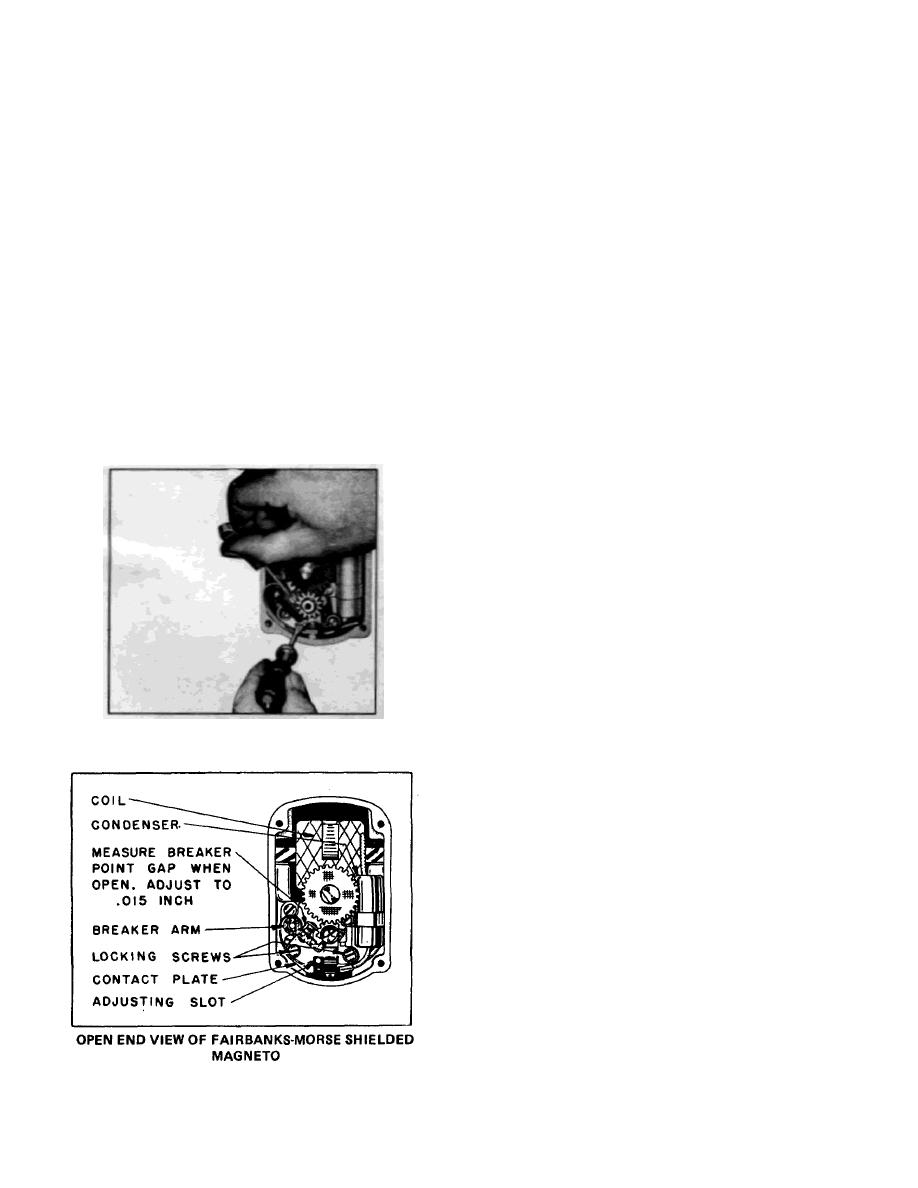
MAGNETO BREAKER POINT ADJUSTMENT
made. Replace magneto end cover carefully so that it
will seal properly. Do not force cover screws too tightly
The shielded magnetos are properly adjusted before
otherwise cover may crack.
leaving factory. The breaker points on the magneto
MAGNETO IGNITION SPARK
should be .015" at full separation. If the spark becomes
If difficulty is experienced in starting the engine or if
weak after continued operation, it may be necessary to
engine misses firing, the strength of the ignition spark
readjust these points. To do this first remove the end
may be tested by disconnecting the No. 1 ignition cable
cover on the magneto. The crankshaft should then be
from the spark plug and holding the terminal about 1/8
rotated by pulsing the starter, (this also rotates the
inch away from the air shroud or any other conveniently
magneto), until the breaker points are wide open. The
located metal part of the engine. Turn the engine over
opening or gap should then be measured with a feeler
and watch for a strong spark discharge, which should
gauge as shown in Fig. 4 and if necessary reset. To
occur during the cycle at the instant the impulse
readjust points, first loosen the locking screws on the
coupling on the magneto snaps. Repeat this check with
contact plate enough so that the plate can be moved.
each of the other ignition cables. If there is a weak
Insert the end of a small screw driver into the adjusting
spark, or none at all, check breaker point opening as
slot at the bottom of the contact plate and open or
mentioned in preceding paragraph under " agneto
M
close the contacts by moving the plate until the proper
Breaker Point Adjustment" If this does not remedy the
.
opening is obtained. See Fig. 5. After tightening the
trouble, it may be necessary to install a new condenser.
locking screws, recheck breaker point gap to make sure
FIRING ORDER
it has not changed. If it is found that the breaker points
The firing order of the cylinders is 1-3-4-2, and the
magneto rotates at one-half engine speed, as is the
case with conventional "in line" engines. The intervals
between the firing of the cylinders is 180 No. 1
.
cylinder is the one nearest to the flywheel in the left
bank of cylinders, when viewed from the flywheel end of
the engine. No. 3 cylinder is the other cylinder in this
bank. No. 2 cylinder is the one nearest to the flywheel
in the right bank of cylinders and No. 4 is the other
cylinder in this bank. The cylinders are numbered from I
to 4 on the air shroud near the spark plugs. The
flywheel end of the engine is designated the front and
the power take-off end, the rear of the engine.
MAGNETO TIMING
The proper spark advance is 230. To check timing with
a neon light, the running spark advance is indicated by
a 3/8 inch slotted hole in the rim of the air intake screen,
FIGURE 4
68 left of the flywheel shroud vertical centerline,
marked VH, or if screen is removed, time to the lower
half of the 1/4 inch elongated hole on the face of
flywheel shroud 230 below the centerline of No. 1 and
No. 3 cylinders as illustrated in Fig. 11. The end of the
'X' marked vane should be whitened with chalk or paint
for this operation.
To Time Magneto to Engine: Remove air intake
screen to expose timing marks on both flywheel and
shroud. See Magneto Timing Diagram, Fig. 6.
Next, remove the spark plug from No. 1 cylinder and
slowly turn the flywheel clockwise, at the same time
holding a finger over the spark plug hole, so that the
compression stroke can be determined from the air
blowing out of the hole.
The flywheel is marked with the letters 'DC' near one of
the air circulating vanes. This vane is further
FIGURE 5
14-2
