TM 5-3895-359-14&P
f. If ampere output is within 10 amperes of rated
output as stamped on alternator frame,
alternator most likely is not defective; recheck
Steps 1 thru 6.
g. If ampere output is not within 10 amperes of
rated output, determine if test hole (Fig. 7) is
accessible. If accessible go to Step h. If not
accessible go to Step 1.
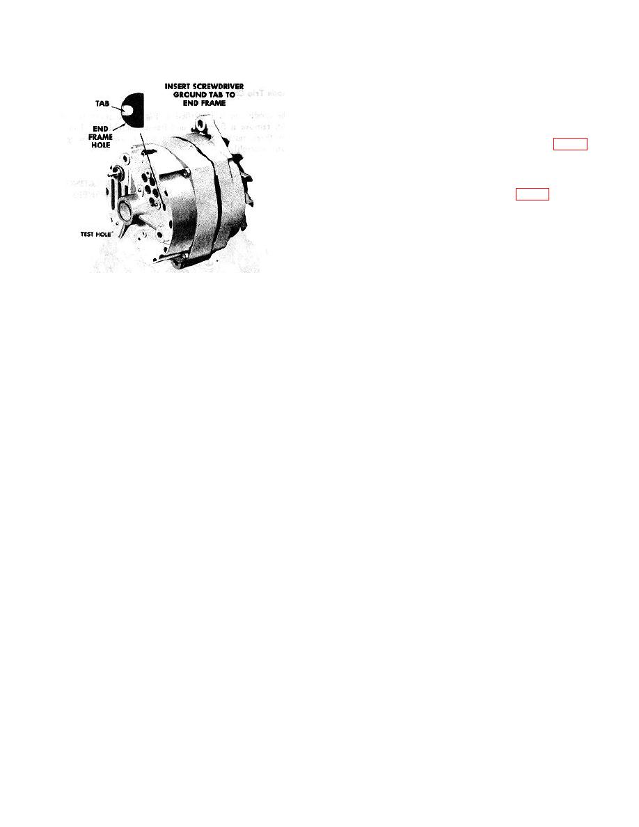
h. Ground the field winding by inserting a
screwdriver into the test hole (Fig. 7).
CAUTION
Tab is within 3/4 inch of casting
surface.
Do
not
force
screwdriver deeper than one inch
into end frame.
Fig. 7 - End Frame Test Hole.
i. Operate engine at moderate speed as required,
ABNORMAL CHARGING SYSTEM OPERATION
and adjust carbon pile as required to obtain
maximum current output.
1. Insure that the undercharged condition has not been
j. If output is within 10 amperes of rated output,
caused by accessories having been left on for extended
check field winding as covered in "REPAIR"
periods.
section, and test regulator with an approved
2. Check the drive belt for proper tension.
regulator tester.
3. If battery defect is suspected, check the battery with
k. If output is not within 10 amperes of rated
suitable test equipment.
output, check the field winding, diode trio,
4. Inspect the wiring for defects. Check all connections
rectifier bridge, and stator as covered in
for tightness and cleanliness, including the slip
"REPAIR" section.
connectors at the alternator and connections at the
l. If test hole is not accessible, disassemble
battery.
alternator and make tests listed in "REPAIR"
5. With ignition switch on and all wiring harness leads
section.
connected, connect a voltmeter from:
REPAIR
a. alternator "BAT" terminal to ground.
b. alternator No. I terminal to ground.
To repair
the
alternator,
observe
the
following
c. alternator No. 2 terminal to ground.
procedure:
A zero reading indicates an open between
voltmeter connection and battery. Repair if
Disassembly
required.
To disassemble the alternator, take out the four thru-
6. With all accessories turned off, connect a voltmeter
bolts, and separate the drive end frame and rotor
across the battery. Operate engine at moderate speed.
assembly from the stator assembly by prying apart with
If voltage is 15.5 or more, remove alternator for repair.
a screwdriver at the stator slot. A scribe mark will help
7. If previous Steps 1 thru 6 check satisfactorily, check
locate the parts in the same position during assembly.
alternator as follows:
After disassembly, place a piece of tape over the slip
ring end frame bearing to prevent entry of dirt and other
a. Disconnect battery ground cable.
foreign material, and also place a piece of tape over the
shaft on the slip ring end. If brushes are to be reused,
b. Connect an ammeter in the circuit at the "BAT"
clean with a soft dry cloth.
terminal of the alternator.
CAUTION
c. Reconnect battery ground cable.
Use pressure sensitive tape and not
d. Turn on accessories. Connect a barbon pile
friction tape which would leave a
across the battery.
gummy deposit on the shaft.
e. Operate engine at moderate speed as required,
and adjust carbon pile as required to obtain
maximum current output.
10-8-5


