TM 5-3895-359-14&P
BATTERY-CHARGING ALTERNATOR
storage battery in a charged condition and to supply
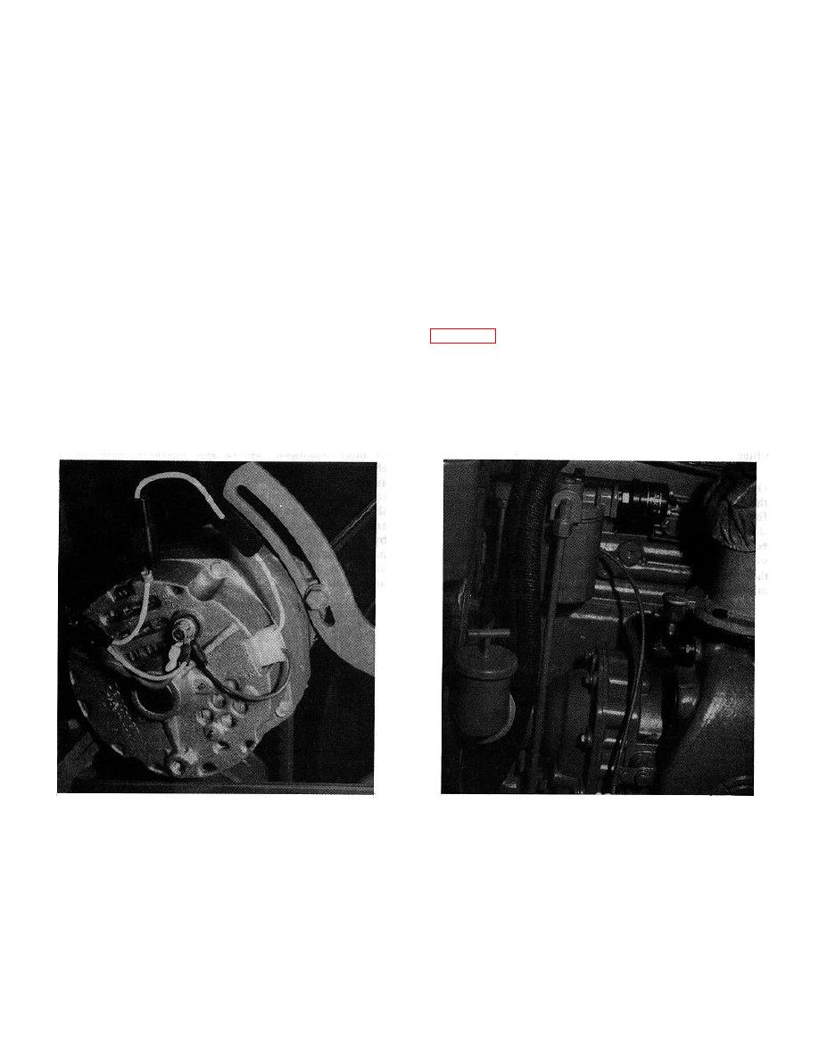
The battery charging circuit consists of alternator with
sufficient current to carry any other electrical load
built-in regulation, protective diode and safety switch,
requirements up to the rated capacity of the generator or
batteries and wiring. The battery-charging alternator
alternator.
(Fig. 1) is introduced into the electrical system to
provide a source of electrical current for maintaining the
HINGE-MOUNTED ALTERNATOR (Belt-driven)
A protective diode is inserted in the wiring harness for
The hinge-mounted alternating current self-rectifying
alternator diode protection, Fig. 1. Additional alternator
alternator is belt driven from the crankshaft pulley by a
protection is provided by the fuel pressure safety switch.
ribbed type V-belt.
The safety switch is mounted on the fuel filter housing
An adequate alternator drive ratio is necessary for an
alternator and the battery. When the engine is running,
engine equipped with extra electrical accessories and
fuel pressure causes the switch diaphram to close the
one that has to operate for extended periods at idle
switch contacts completing the circuit between alternator
speeds. Diodes, built into the slip ring end frame, rectify
and battery. When the engine is stopped, the absence
the three phase A.C. voltage to provide D.C. voltage at
of fuel pressure allows the contacts to open the circuit
the battery terminal of the alternator, thereby eliminating
between alternator and battery.
the need for an external rectifier.
Fig.1 - Hinge-Mounted Alternator.
Fig. 2 - Pressure Safety Switch.
10-8-2


