TM 5-3895-359-14&P
TROUBLESHOOTING PROCEDURE
(Close adherence to the following procedures in the
order presented will lead to the location and correction
of charging system defects in the shortest possible time.
Only a portion of these procedures need be performed.
It will never be necessary to perform all the procedures
in order to locate the trouble.)
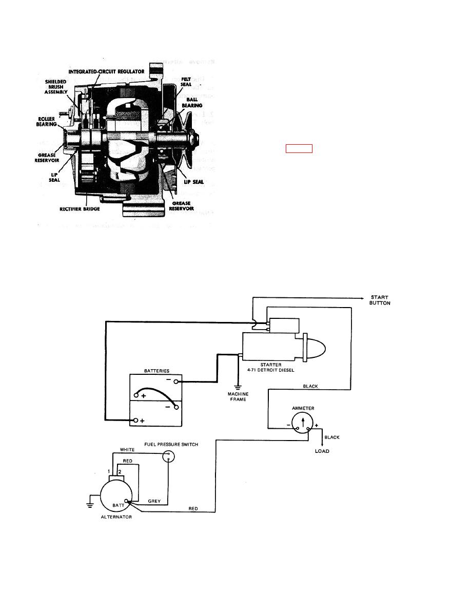
A basic wiring diagram showing lead connections is
shown in Fig. 6. To avoid damage to the electrical
equipment, always observe the following precautions:
Do not polarize the alternator.
Do not short across or ground any of the terminals in
the charging circuit, except as specifically instructed
herein.
NEVER operate the alternator with the output
terminal open-circuited.
Fig. 5 - Cross Sectional View.
Make sure the alternator and battery have the same
ground polarity.
When connecting a charge or a booster battery to
the vehicle battery, connect negative to negative,
and positive to positive.
Fig. 6 - Charging Circuit.
10-8-4


