TM 5-3895-359-14&P
NOTE: Tightening the cylinder head
bolts will not correct a leaking
compression gasket or seal. The head
must be removed and the damaged
gasket or seal replaced.
9. Tighten the two flywheel housing attaching bolts
directly below the rear lifter bracket. Install a new
gasket and secure the rear engine lifter bracket to the
cylinder head and the flywheel housing. Tighten the
bolts to 55-60 lb-ft (75-81 Nm) torque. (Fig. 14).
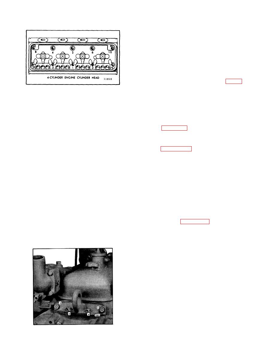
Fig. 13 Cylinder Head Bolt Tightening Sequence
10. Affix a new gasket to the front lifter bracket (or vent
casting) and attach the bracket to the cylinder head and
7. After the head is in place, remove the guide studs
the balance weight cover. Tighten the bolts in the same
and chain hoist and install the remaining bolts, running
sequence and to the same torque as on the rear lifter
all bolts down snug tight with a speed handle (15-20 lb-ft
bracket bolts.
or 20-27 Nm torque). However, before tightening the
bolts, loosen the lifter bracket-to-cylinder head attaching
11. If the fuel injectors were not previously installed,
bolts, otherwise the head may be prevented from
refer to Page 10-3-8 or 10-3-23 and install them at this
seating properly on the cylinder block.
A similar
time.
condition could exist if the exhaust manifold is attached
to cylinder head. Clearance must be assured between
12. Tighten the rocker arm bracket bolts to the specified
the exhaust manifold and the bosses on the cylinder
torque (Page 10-2-140).
block.
13. Align the fuel pipes and connect them to the
8. Tighten the bolts to 175-185 lb-ft (238-251 Nm)
injectors and the fuel connectors. Use socket J 8932-01
torque in 50 lb-ft (68 Nm) increments with a torque
to tighten the connections to 12-15 lb-ft (16-20 Nm)
wrench, in the sequence shown in Fig. 13. Repeat the
torque.
tightening sequence at least once, because the first
CAUTION: Do not bend the fuel pipes
bolts tightened in the sequence tend to lose significant
and do not exceed the specified torque.
clamp load during tightening of the remaining bolts.
Excessive tightening will twist or
Apply a steady pressure for two or three seconds at the
fracture the flared ends of the fuel pipes
prescribed torque to allow the bolts to turn while the
and result in leaks.
Lubricating oil
gaskets yield to their final designed thickness. Begin on
diluted by fuel oil can cause serious
the cam follower side of the head to take up tension in
damage to the engine bearings (refer to
the push rod springs. Tighten the bolts to the high side
Pressurize Fuel System Check for
of the torque specification, but do not exceed the limit or
Leaks on Page 10-3-56).
the bolts may stretch beyond their elastic limits.
Attempting to tighten the bolts in one step may result in
14. Set the injector control tube assembly in place on
trouble and consequent loss of time in diagnosis and
the cylinder head and install the attaching bolts linger
correction of difficulties, such as compression leaks,
tight. When positioning the control tube. be sure the
when the engine is put into operation.
ball end of each injector rack control lever engages the
slot in the corresponding injector control rack. With one
end of the control tube return spring hooked around an
injector rack control lever and the other end hooked
around a control tube bracket, tighten the bracket bolts
to 10-12 Ib-ft (14-16 Nm) torque.
15. After tightening the bolts, revolve the injector
control tube to be sure the return spring pulls the injector
racks out (no-fuel position) after they have been moved
all the way in (full-fuel position). Since the injector
control tube is mounted in self-aligning bearings, tapping
the tube lightly will remove any bind that may exist. The
injector racks must return to
Fig. 14. Lifter Bracket Bolt Tightening Sequence
10-2-27


