
TM 5-3895-359-14&P
CYLINDER BLOCK
Each cylinder liner is retained in the block by a flange at
its upper end. The liner flange rests on a cast iron insert
structural part of the engine. Transverse members, cast
located in the counterbore in the block bore. An
integrally, provide rigidity and strength and ensure
individual compression gasket is used at each cylinder.
alignment of the block bores and bearings under load.
Cylinder blocks for the three, four and six-cylinder
When the cylinder head is installed, the gaskets and
engines are identical in design and dimensions except
seal rings compress sufficiently to form a tight metal-to-
for length. The two ends of the block are similar, so the
metal contact between the head and block.
flywheel housing and the gear train can be assembled to
either end.
New service replacement cylinder block assemblies
include the main bearing caps and bolts, dowels and the
The block is bored to receive replaceable cylinder liners.
necessary plugs.
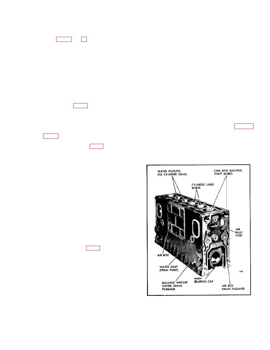
Water jackets, which extend the full length of the bores,
are divided into upper and lower sections which are
Since the cylinder block is the main structural part of the
connected by hollow struts (Fig. 2). Coolant from the
engine, the various sub-assemblies must be removed
pump enters at the bottom of each water jacket and
from the cylinder block when an engine is overhauled.
leaves at the top of the block through holes which
register with corresponding openings in the cylinder
The hydraulically operated overhaul stand (Fig. 5)
head.
provides a convenient support when stripping a cylinder
block. The engine is mounted in an upright position. It
An air box (Fig. 2) surrounding the water jackets
may then be tipped on its side, rotated in either direction
conducts the air from the blower to the air inlet ports in
90 or 180 c where it is locked in place and then, if
the cylinder liners. Air box openings (Fig. 3) on the side
desired, tipped back with either end or the oil pan side
of the block opposite to the blower provide access to the
up.
air box and permit inspection of the pistons and
compression rings through the air inlet ports in the
cylinder walls.
The camshaft and balance shaft bores are located on
opposite sides near the top of the block.
The upper halves of the main bearing supports are cast
integral with the block. The main bearing bores are line-
bored with the bearing caps in place to ensure
longitudinal alignment. Drilled passages in the block
carry the lubricating oil to all moving parts of the engine,
eliminating the need for external piping.
The perimeter of the top surface of the cylinder block is
grooved, outside of the cam pockets, to accommodate a
block-to-head oil seal ring. The top surface of the block
is also counterbored at each water or oil passage to
accommodate individual seal rings (Fig. 4).
Fig. 1 - Typical Cylinder Block
10-2-3
