TM 5-3895-359-14&P
SUBSECTION 9 HYDRAULIC CYLINDERS
7. Clean and inspect all parts for scoring and corrosion.
All packings and "O" rings should be replaced. If inside
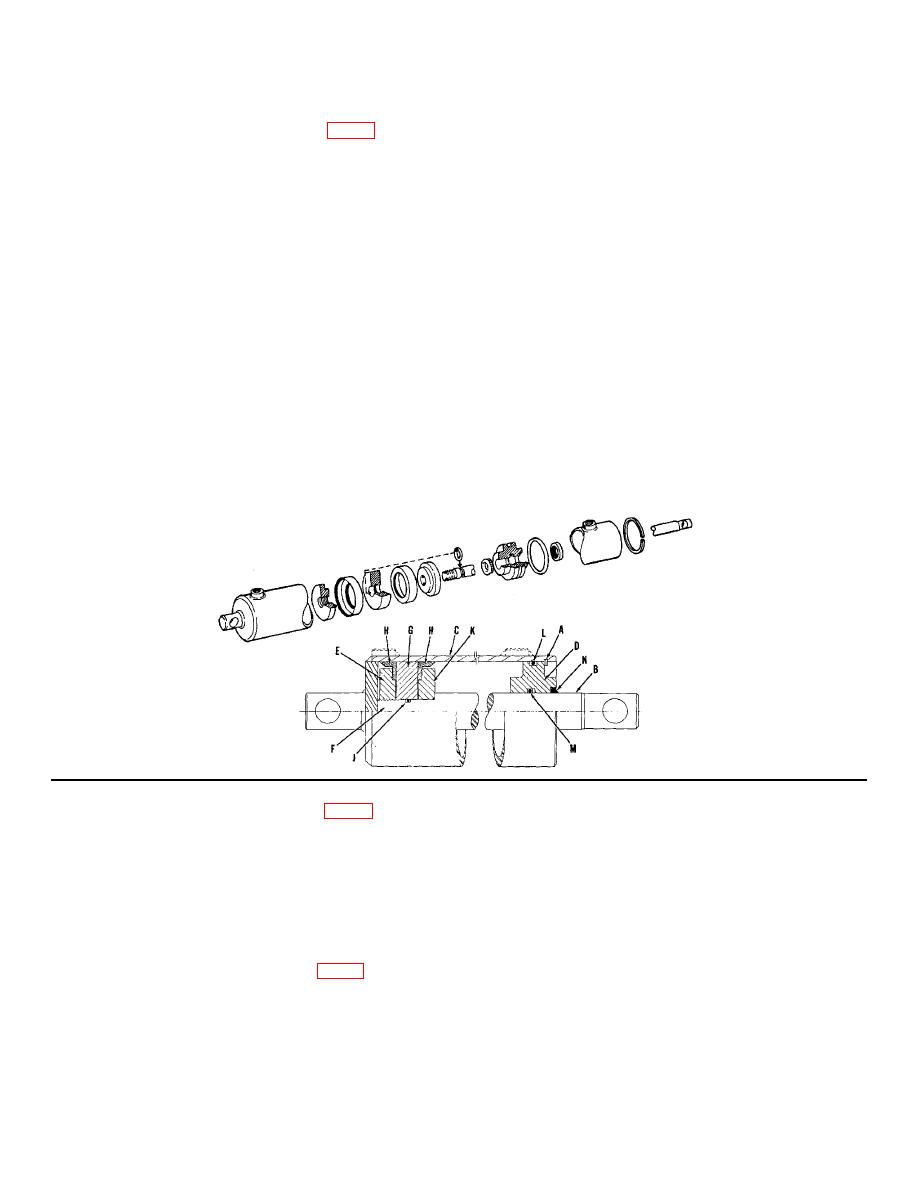
CRANE LIFT HYDRAULIC CYLINDER (Fig. 1)
cylinder is scratched, it may be honed to 0.040"
oversize. If unable to clean up at this dimension,
replace cylinder.
The hydraulic ram is assembled to the machine frame
and crane with two pins. Lower the rotor and hood
8. Lubricate all parts before reassembly.
assembly and block crane in this position.
9. Assembly Replace "O" ring (M). Slide gland bushing
1. Remove hydraulic hoses from cylinder. Plug or cap
(D) on rod (F). Follow with packing adapter (K), "O" ring
hoses.
(J), first packing (K), piston (G), second packing (H) and
thread on packing adapter (E). Tighten and prick punch
2. Remove the ram pins and dismount ram for bench
to rod (F).
work.
10. Replace "O" ring (L) in gland bushing (D). Slide
3. Clean ram externally and hold in vise at the base
piston assembly (B) into cylinder. Tap gland bushing
end.
(D) into cylinder until it bottoms. Replace snap ring (A)
4. Remove snap ring (A) from rod end of cylinder.
and dirt seal (N).
Piston assembly (B) may now be forced from cylinder
11. Reassemble on machine. Connect hoses. Check
(C) along with gland bushing (D).
for leakage and operation. Air is purged from cylinder
by operation. Add fresh oil to hydraulic tank to level
5. Unthread packing adapter (E) from rod (F). Packings
mark.
(H), piston (G), "O" ring (J) and packing adapter (K) may
now be removed.
6. Slide gland bushing (D) off rod and remove "O" rings
(L) and (M) and dirt seal (N).
FIGURE 1
2. Clean hydraulic hose couplings at cylinder before
TAILBOARD HYDRAULIC CYLINDER (Fig. 2)
unthreading hoses. Disconnect hydraulic hoses from
Each end of the double acting cylinder is pinned to a
cylinder. Remove bolts or pins at base and rod end of
non-adjustable base. No adjustment is required. A self-
cylinder and remove cylinder.
aligning bushing in each rod end allows the cylinder to
3. Hold cylinder in a vise, gripped lightly at the base
pivot with the movement of the tailboard.
end.
In the event the cylinder is in need of repair, a repair kit
4. Remove snap ring (A), pull piston and rod assembly
is available from the factory. Refer to Parts Book for
(B) out against the cylinder head (C) by tapping against
parts kit number.
shoulder of rod base (D), this will free the cylinder head
Overhaul of the cylinder is as follows: (Fig. 2)
(C) from cylinder (E).
1. Make sure the cylinder is not under pressure before
5. Remove nut (F) from shaft (G). The piston (H) and
removing.
cylinder head (C) may now be slid off shaft (G).
9-1


