
TM 5-3895-359-14&P
REPLACING CENTER SECTION ASSEMBLIES IN
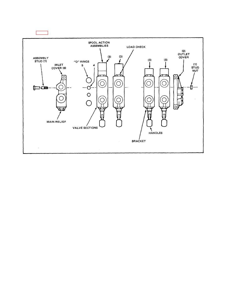
THE VALVE (Fig. 4)
FIGURE 4 Model V20 Directional Control Valve, Typical Main Assembly
For the purpose of these instructions, we shall consider
5. Next, valve sections may be disassembled by
the section containing the main relief valve the left side
sliding the sections (2), (3), (6) along the
of the valve.
assembly studs.
1. If the valve is to be reassembled in the same
6. Thoroughly clean the "0" ring counterbores and
order, it is suggested that before disassembling,
the ground surface of each section. Place new
each section be marked numerically so that they
"O" ring seals (4), (5) in proper counterbores.
may be returned to the same sequence when
For better sealing, it is suggested that all "O"
reassembled.
rings used in the counterbores be replaced with
2. If valve has been removed from equipment, it is
new parts.
advisable to mount valve vertically in a vise to
7. Replace the sections on assembly studs with the
facilitate disassembly and assembly.
"O" ring counterbores facing right end of valve.
3. On the right end of the valve there may be a
Use care in replacing sections so the section
power beyond sleeve, conversion plug or closed
"O" rings are not dislodged from the
center plug installed. These must be removed
counterbores.
before the valve can be disassembled.
8. When all sections are assembled on assembly
4. Remove the three assembly stud nuts (1) from
studs, tighten the assembly stud nuts or bolts
right end section.
evenly to 32 ft. lbs. torque, NO MORE, NO
LESS, otherwise spools may bind or stick.
8-4
