TM 5-3895-359-14&P
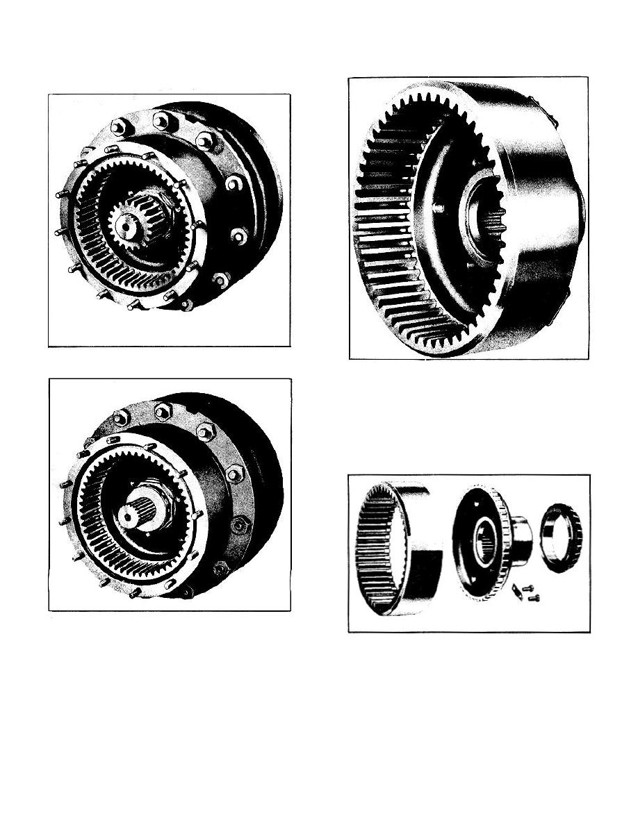
REMOVE THE FLOATING RING GEAR ASSEMBLY
a. Remove the lock ring from end of axle shaft.
g. Remove the floating ring gear assembly. Puller
screw holes are provided in the ring gear hub flange to
start gear.
1. The floating ring gear is splined to the ring gear hub
and secured by four evenly spaced plates, each plate
being attached by two cap screws which are lockwired
together.
2. The outer wheel bearing is mounted on the ring gear
hub.
b. Remove the axle shaft sun gear.
c. Remove the sun gear thrust washer.
h. Separate the ring gear and ring gear hub by
d. Remove the axle shaft.
removing lock wire, cap screws and plates.
e. Remove the wheel bearing adjusting nut lock,
i. Remove outer wheel bearing from ring gear
by removing the two capscrews and lock plate.
hub.
f. Remove the wheel bearing adjusting nut.
j. The ring gear hub assembly is made up of the
hub and a hardened ring sleeve insert which is pressed
into the hub from the outer side.
5-3


