
TM 5-3895-359-14&P
CHECK AND ADJUST GEAR LASH
A. Install differential and gear assembly and assemble
cover using new gasket with six bolts equally spaced.
Tighten to specified torque.
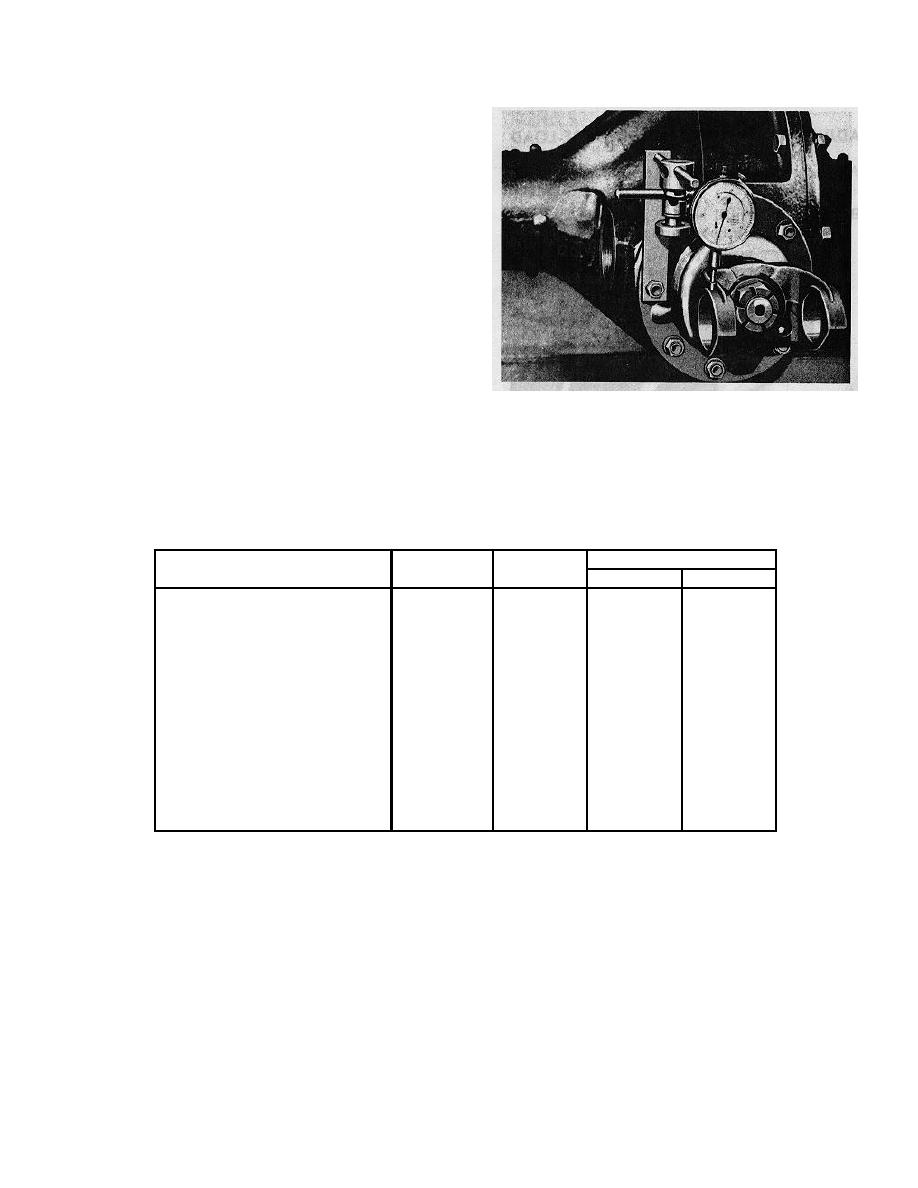
B. Check gear lash with dial indicator on universal joint
yoke 2" from pinion shaft center. An indicator reading of
between .013" and .033" will show the recommended
backlash of between .006" and .012" is present in the
gear set.
C. Transpose spacers used in both the case and cover,
decreasing the thickness of the spacer used on the side
in the direction which the gear is to be moved and
increasing the thickness of the opposite spacer exactly
the same amount as required to obtain the correct gear
lash.
D. Install remaining bolts, washers and nuts in housing
assembly and tighten all nuts in bolt circle to specified
torque.
LUBRICATION
Fill axle to correct level with specified lubricant and lubricate universal joint. Refer to lubrication chart on page 15-1.
TORQUE SPECIFICATIONS
DIAM-
NO.
TORQUE-LB. -- FT.
LOCATION
ETER
THREADS
Min.
Max.
Cover to case bolt nuts
3/8"
16
27
35
3/8"
24
31
39
7/16"
20
42
54
1/2"
20
75
96
Pinion cage cap screws
3/8"
16
27
35
and stud nuts
3/8"
24
31
39
7/16"
20
42
54
9/16"
12
94
120
Differential case bolt nuts
3/8"
16
33
43
and cap screws
1/2"
13
81
104
1/2"
20
92
118
Pinion shaft nuts
7/8"
20
175
200
1"
20
300
400
Gear to case cap screws
3/8"
24
38
49
Torques given apply to parts coated with machine oil; for dry (or "as received") parts increase torques 10%;
for parts coated with multi-purpose gear oil decrease torques 10%. Nuts on studs to use same torque as for
driving the stud.
4-20
