
TM 5-3895-342-34
When replacing the shell bearings, be sure and replace a
complete bearing (both halves). Be sure piston and
connecting rod assemblies are put back into the same
bore from which they were removed. The piston skirt is
camground to an elliptical contour. Clearance between
the piston and cylinder must be measured at the center
of the thrust face of the piton skirt. Refer to table 1-1.
The thrust faces on the piston skin are 90 degrees from
the axis of the piston pin hole. When reassembling the
piston and connecting rod to the engine, be sure the
arrow on the top of the piston is pointing in the direction
of crankshaft rotation. (Clockwise when viewing the
flywheel end of the engine. Tighten connecting rod nuts
22 to 24 foot pounds torque.
e. Installation.
Install the baffle plates and
connecting rods and piston assemblies in reverse of
instructions in subparagraph a above.
Note. Install piston in number one and three
cylinder so that the slit in the piston skirts face the enter
of the engine. The slits in pistons two and four must face
away from the center of the engine.
3-17. Crankshaft Assembly
a.
Removal.
(1) Remove engine (para 2-9).
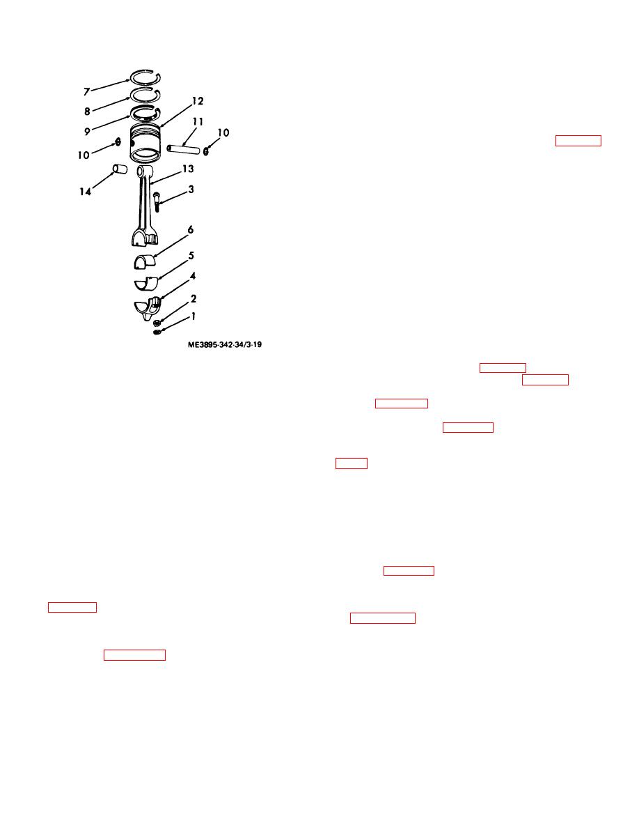
1. Nut, Stamped, 5/16-24
(2) Remove clutch assembly (para 3-7).
2. Nut, Hex 5/1624
(3) Remove timing gears and gear cover
3. Bolt, Shoulder, 5/16-24
spacer. (para 3-13).
4. Cap
(4) Remove baffle plates, and connecting rod
5. Lower Half Bearing
and piston assemblies (para 3-16).
6. Upper Half Bearing
(5) Remove the crankshaft assembly from the
7. Compression Ring
crankcase in numerical sequence as illustrated in figure
8. Scraper Ring
9. Oil Ring
these are required to give the proper end play to the
10. Retainer Ring
tapered roller main bearings on the crankshaft. The end
11. Piston
play should be .002 to .004 inch when engine is cold.
12. Piston
There is practically no wear on the bearings so that no
13. Connecting Rod
readjustment is necessary after proper assembly.
14. Sleeve Bearing
b. Cleaning, Inspection and Repair.
(1) Clean all parts with cleaning solvent.
Figure 3-19. Piston assembly, exploded view.
(2) Inspect all parts for wear and damage.
Refer to table 1-1 for wear limit and dimensions.
c.
Cleaning, Inspection and Repair.
Replace worn or damaged parts.
(1) Clean a parts with a leaning solvent.
c. Reassembly.
Reassemble the crankshaft
(2) Inspect all parts for wear or damage. refer
assembly in reverse of numerical sequence as illustrated
to table 1-1 for wear limits and connections. Replace
in figure 3-20. When reassembling crankshaft, the
worn or damaged parts.
timing marks on the crankshaft gear and the camshaft
d. Reassembly. Reassemble the connecting rod
gear must be matched. Tighten main bearing plate
and piston assemblies reverse of numerical sequence as
capscrews 25 to 30 foot pounds torque.
illustrated in figure 3-19. The connecting rods have
removable shell bearings and care should be take in
reassembly that they are in place in the rod and cap.
3-23

