TM 5-3895-369-14
NOTE
Mounting bracket is shown in art and is
optional for the following steps.
(7)
(8)
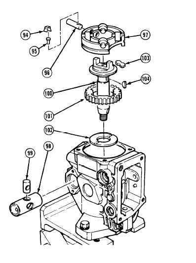
Assemble drive shaft and spur gear as
follows:
(a)
(b)
(c)
(d)
(e)
Immerse spur gear (101) in calibration
fluid.
Install spur gear (101) on drive
shaft (100) aligning notches.
Apply grease to four coupling
inserts (103).
Install four coupling (103) inserts.
If removed, install two keys (104).
Immerse washer (102) in calibration fluid.
Ensure that drive shaft key way are aligned
with fuel pump housing key way. Failure
to do so will damage drive shaft and fuel
pump housing.
(9)
Install washer (102) on drive shaft (100) and
install drive shaft.
(10)
Apply grease to plug (99).
(11)
Install plug (99) with holes aligned with timing piston (98) holes.
(12)
Immerse timing piston (98) in calibration fluid.
(13)
Install timing piston (98) with high pressure side facing left and hole through plug (99) facing direction of
roller holder pin (96) as shown.
(14)
If removed, immerse holder pin (96) in calibration fluid.
(15)
Install holder pin (96) in roller bearing (97) with hole facing up as shown.
5-252


