
TM 5-3895-369-14
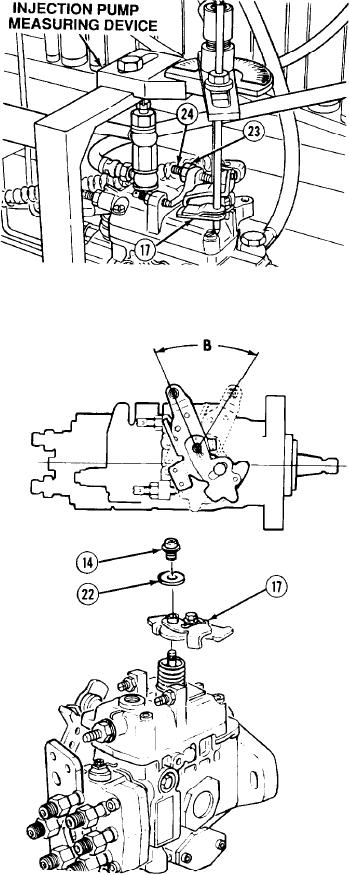
(9) Adjust no-load maximum speed injection
quantity as follows:
(a) Install injection pump measuring
device and fix lower control lever
assembly (17) in maximum speed
position.
(b) Operate pump at no-load maximum
speed specified in calibration data.
Measure injection quantity. If quantity
(c)
is within limits, go to step (9) (d). If
quantity is not within limits, loosen nut
(23) and adjust maximum speed screw
(24) to get correct measurement.
Tighten nut 52 to 78 lb-in. (6 - 9 Nm).
(d) Measure lower control lever assembly
(17) at position B. If angle is within
limits, go to step (10). If angle is not
within limits, remove injection pump
measuring device, flange nut (14), and
intermediate disc (22).
(e) Position lower control lever assembly
(17) to get correct angle and install
intermediate disc (22), flange nut (14),
and injection pump measuring device.
Tighten nut 60 to 86 lb-in. (7 - 10 Nm).
Repeat steps (a) to (d) and (7) (a)
(f)
to (7) (c).
NOTE
Note location of control lever assembly
and scribe marks on control shaft.
(10) Remove injection pump measuring device,
flange nut (14), intermediate disc (22), and
lower control lever assembly (17).
5-271