
TM 5-3895-359-14&P
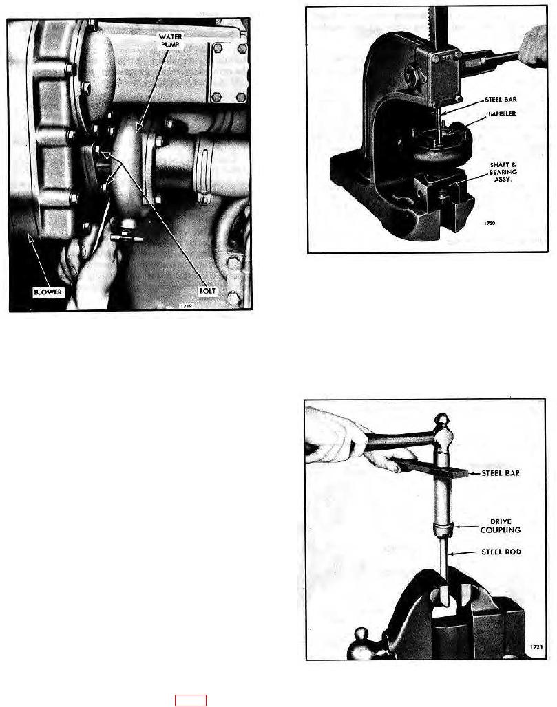
Fig. 4 Pressing Pump Shaft from Impeller
Inspection
Fig. 3- Loosening Inner Pump-to-Blower Attaching
Clean all of the parts except the shaft and bearing
Bolt with Tool J 4242
assembly. The sealed type pump shaft bearing must
not be immersed in a cleaning fluid since dirt may be
Disassemble Water Pump
washed in and the fluid cannot be entirely removed.
1. Remove the pump cover and gasket.
NOTE:
Clean the corrosion from around the
impeller and shaft before separating
the shaft and bearing assembly from
the impeller, seal and pump body.
2. Support the pump on its mounting flange in an arbor
press (Fig. 4). Place a short steel rod on the end of the
shaft and press the shaft and bearing assembly from the
impeller, seal and pump body.
3. Remove the impeller and seal assembly from the
pump body.
CAUTION:
When removing the impeller, protect
the ceramic insert from damage at all
times during pump overhaul. Always
lay the impeller on the bench with
the ceramic insert up to prevent
Fig. 5 - Removing Pump Drive Coupling from Shaft
damage to the insert.
with Tool J 1930
4. If necessary, remove the pump drive coupling from
the shaft with tool J 1930 as shown in Fig. 5.
10-6-7