TM 5-3895-359-14&P
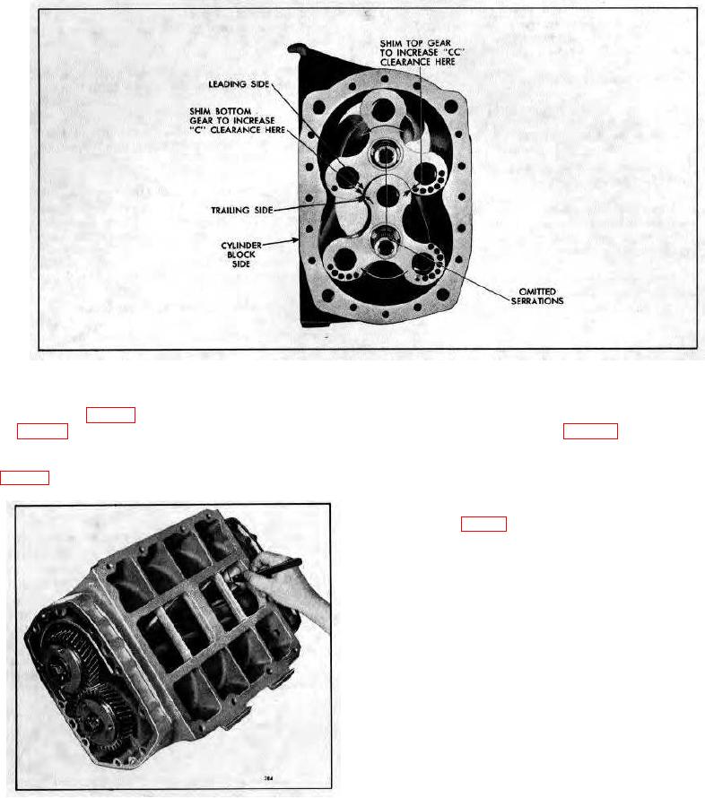
Fig. 18 - Diagram Showing Proper Location of Shims for Correct Rotor Lobe Clearances.
5. Check the clearance between each rotor lobe and the
4. Determine the minimum clearances at points "A" and
blower housing at both the inlet and outlet side -twelve
"B" shown in Fig. 17. Insert the feeler gages, as shown
measurements in all. See Fig. 17 for the minimum
in Fig. 19, between the end plates and the ends of the
clearances.
rotors. This operation must be performed at the ends of
each lobe, making twelve measurements in all. See
Fig. 17 for the minimum clearances.
After the blower rotors, are timed, complete the
assembly of the blower as outlined below.
2. Refer to Fig. 7 and attach the blower rotor drive hub
(20) and drive hub plates (115) to the blower gears as
follows:
a. If removed, attach the rotor drive hub plates
(115) to the drive hub (20) with three bolts (22),
lock washers and plain washers. Tighten the
bolts to 25-30 lb-ft (34-41 Nm) torque.
b. Attach the rotor drive hub and drive plates to the
right-hand helix rotor timing gear with three bolts
(21), lock washers, plain washers and three
spacers (116) between the plates and the face
of the gear. Tighten the bolts to 25-30 lb-ft (34-
41 Nm) torque.
c. Check the runout of the splines in the rotor drive
hub with an indicator. The spline runout must
Fig. 19 - Measuring End Clearance Between Blower
not exceed .020" total indicator reading.
Rotors and End Plate .
3. Affix a new gasket (32) to the blower rear end plate
cover (29).
10-4-19

