
TM 5-3895-359-14&P
c. Position the end plate in front of the blower
housing with the flat finished face of the end
plate facing the housing and the end marked
TOP facing the flanged side of the housing.
Then, start the dowel pins straight into the dowel
pin holes in the housing. Push or tap the end
plate against the housing.
d. Insert the two fillister head screws through the
end plate and thread them into the housing.
Tighten the screws to 5-10 lb-ft (7-14 Nm)
torque. Do not use lock washers on these
screws.
2. Assemble the blower rotors in the blower housing
and front end plate as follows:
The rotors must be assembled in the blower housing
with the omitted serrations in the rotor shafts aligned as
shown in Fig. 18.
NOTE
The housing used in N Blower
assemblies
are
stamped
for
identification with the letter "E", near
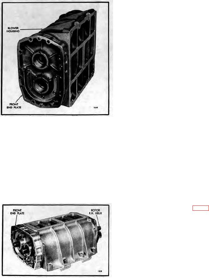
Fig. 10 - Position of Blower Front End Plate on
the top of the housing.
Housing.
a. Place an oil seal pilot J 6270-5 on the short
(non-splined) end of each rotor shaft. Then,
One end plate should be assembled to the front end of
place the rotors in mesh with the omitted
the blower housing first and the other plate should be
serrations in the shafts in alignment as shown in
assembled to the rear of the blower housing after the
Fig. 18.
rotors are in place. Attach an end plate to the front of
NOTE
the blower housing as follows:
When oversize oil seals are used in
a. Check the dowel pins. The dowel pins must
the blower end plate, use oil seal
project .380" from the flat inner face, and .270"
spacer installers J 6270-28 for the oil
from the outer face of the front end plate to
seal pilots in place of J 6270-5.
assure proper alignment of the end plate to the
b. Insert the blower rotors with oil seal pilots
housing and the cover to the end plate.
straight into the blower housing with the right-
b. Place the blower housing on a bench with the
hand helix rotor at the top, flange, side of the
top of the housing up, and the front end of the
housing. Then, push the rotor shafts and oil
housing facing the outside of the bench.
seal pilots on through the oil seal in the front
end plate as shown in Fig. 11.
c. Remove the oil seal pilots from the rotor shafts.
3. Attach the blower rear end plate to the blower
housing as follows:
a. Reverse the blower housing on the bench (rear
end of housing facing the outside of the bench).
b. Place an oil seal pilot J 6270-5 on the serrated
end of each rotor shaft.
NOTE
When oversize oil seals are used in
the blower end plate, use oil seal
spacer installers J 6270-28 for the oil
seal pilots in place of J 6270-5.
Fig. 11 - Assembling Blower Rotors into Housing
and Front End Plate (Lip Type Oil Seals) using Tool
J 6270-5.
10-4-14