
TM 5-3895-359-14&P
Start a new needle bearing straight into the bearing bore
of the cover with number on the bearing up.
Then insert bearing installer J 21068 in the bearing and
press the bearing in until the shoulder on the tool
contacts the cover (Fig. 11).
2. Reverse the governor cover on the bed of the press
(inner face of cover up). Start the second bearing
straight into the bore of the cover with the bearing
number up. Press the bearing in flush with the cover
with tool J 21068.
NOTE: Do not use impact tools to install needle
bearings.
3. Pack the needle bearings with grease. If the cover
contained a bushing which was not removed, lubricate it
with clean engine oil. Insert the throttle shaft through
the bearing or bushing.
Fig. 8. Removing Operating Shaft from Operating
Lever
4. Insert a seal ring over the throttle shaft and into the
counterbore against the upper bearing. Place the
Assemble Governor Cover
retainer over the shaft and against the seal ring.
1. If new needle bearings are to be installed in the
5. Locate the lock ring in the groove of the throttle
governor cover, place the governor cover on the bed of
shaft.
an arbor press with the inner face of the cover down.
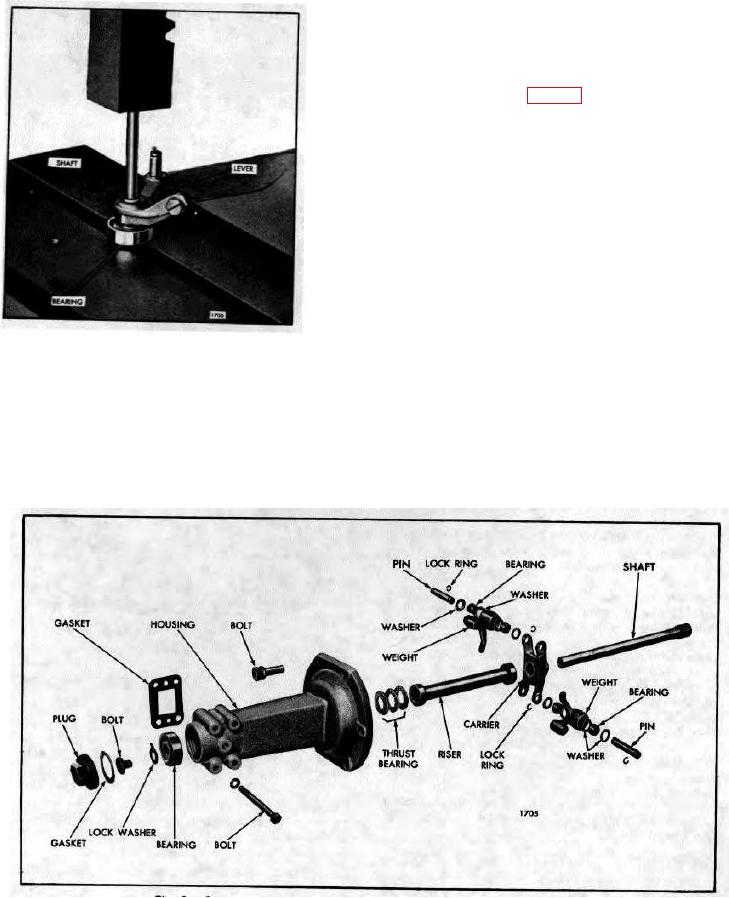
Fig. 9. Governor Weight Housing Details and Relative Location of Parts
10-3-44